Introduction
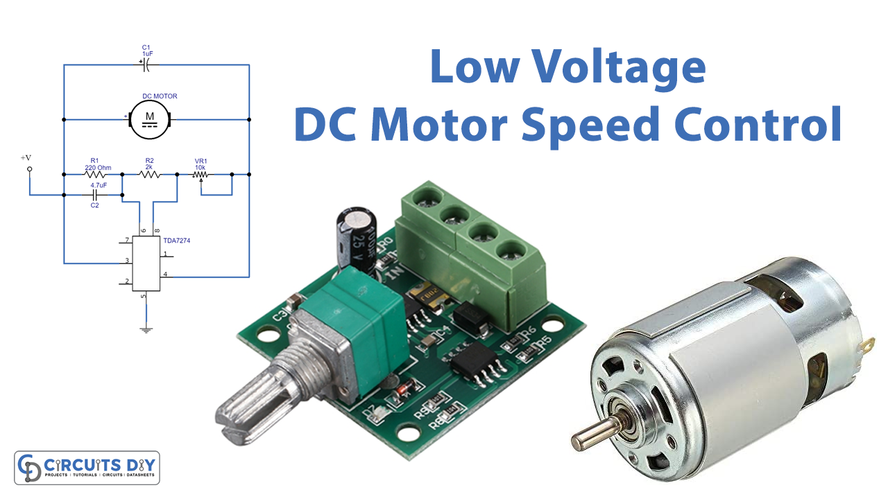
DC devices are extensively used in many commercial and industrial sectors and so are DC motors. Moreover, in many places, the accurate speed of these machines is certainly required. And, as you know that every industry employs mechanical machines where one energy converts into another. For instance, take the example of the electric motor converting electrical energy into mechanical. Hence, the speed of the motor may get varied with the number of tasks performed and that’s why it is important to control the speed. However, in this article, we will discuss the DC motor speed controller that can control low voltages only. So, in this tutorial, we are going to create a “Low voltage DC motor speed control circuit”
Hardware Required
| S.no | Component | Value | Qty |
|---|---|---|---|
| 1. | IC | TDA7274 | 1 |
| 2. | DC Motor | – | 1 |
| 3. | Potentiometer | 10KΩ | 1 |
| 4. | Electrolytic Capacitor | 1uF, 4.7uF | 1, 1 |
| 5. | Resistor | 220Ω, 2KΩ | 1, 1 |
| 6. | 2-Pin Connector | – | 1 |
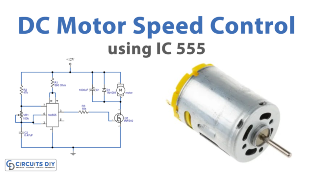
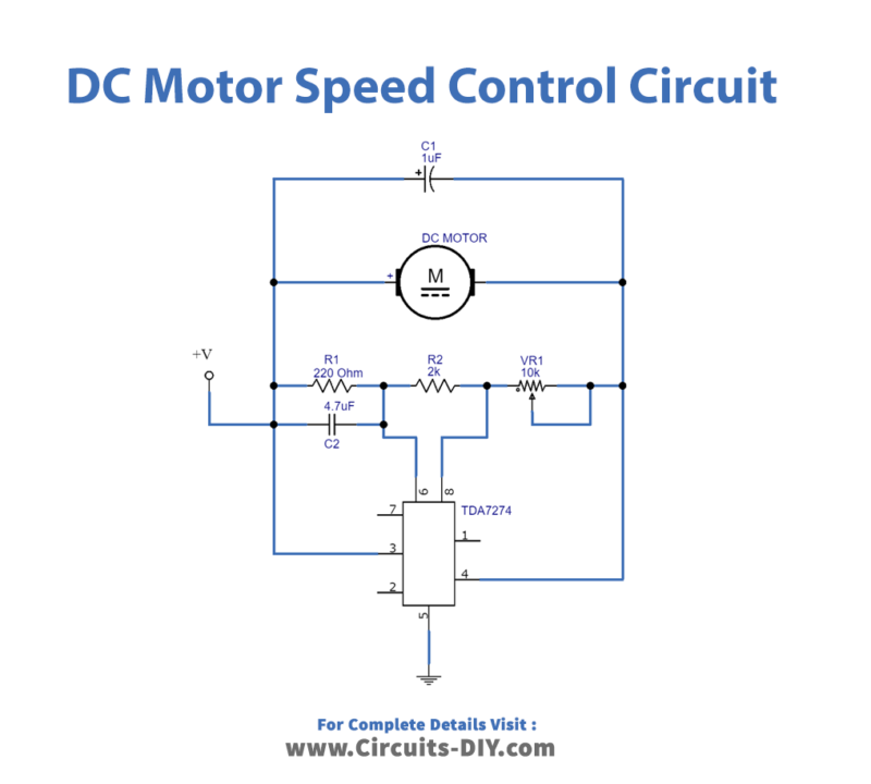
Circuit Diagram
Working Explanation
This Low voltage DC motor speed control circuit uses the low voltage DC control TDA 7274 IC. The input is given at the supply pin 3 of an IC. The potentiometer is also there at the control pin 8. The pot is also wired to the reference pin six through resistor R2. The speed of the motor gets varied by varying this potentiometer. The motor is connected between the output pin 4 and the input supply.
Application and Uses
- Mainly, suitable for low-voltage applications.
- Microcasstes use this circuit
- Moreover, used in radio cassette players.
- Further, in some other consumer products.