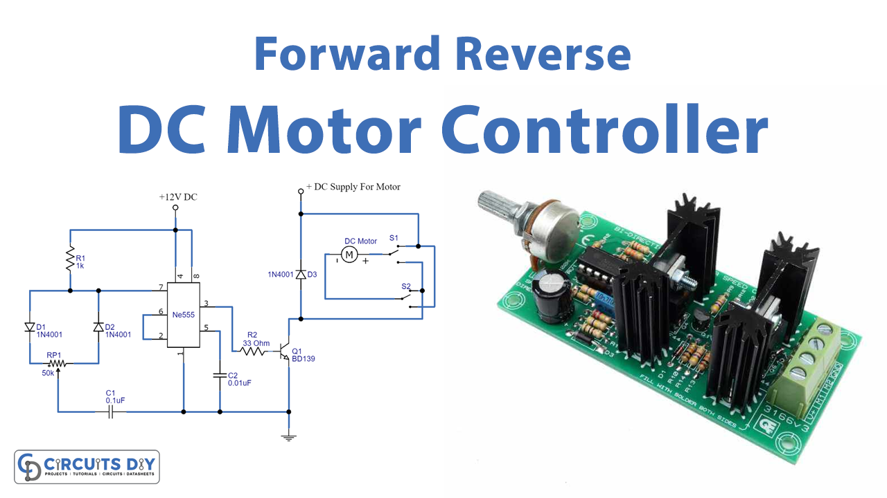
Introduction
DC motor technology has advanced significantly and is now used extensively across various sectors. One of the most practical aspects of the motor is its ability to control speed. You may change the motor’s speed to suit your needs and achieve the desired function by adjusting the motor’s speed. Thus, DC motor speed can be controlled in both forward and reverse directions. So, in this tutorial, we will make a “forward reverse DC motor control diagram with timer IC.”
One might be curious as to how a DC motor works and why understanding DC motor speed control is crucial. So, just so you know, speed control for the machine affects how quickly the motor rotates, directly affecting how well the device works, and is crucial for performance and results.
Hardware Required
| S.no | Component | Value | Qty |
|---|---|---|---|
| 1. | IC | NE555 Timer | 1 |
| 2. | NPN Transistor | BD139 | 1 |
| 3. | Diode | 1N4001 | 3 |
| 4. | Potentiometer | 50K | 1 |
| 5 | DC Motor | – | 1 |
| 6. | DPDT Switch | – | 1 |
| 7. | White LED Array | – | 1 |
| 8. | DC Supply | 12v | 1 |
| 9. | Ceramic Capacitor | 0.1uF, 0.01uF | 1, 1 |
| 10. | Resistor | 1K, 33 Ohm | 1, 1 |
Circuit Diagram
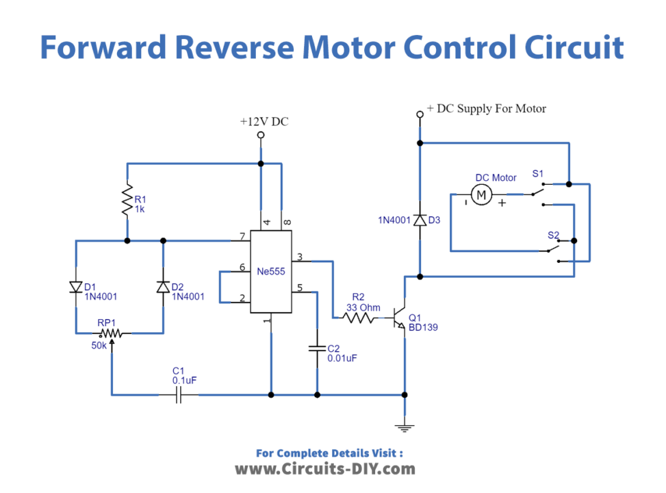
Working Explanation
The above given Forward Reverse DC, motor control diagram contains a DPDT switch that connects the DC motor to the supply and allows forward and reversed spinning of the DC motor by changing the power supply’s polarity delivered to it. There is no increase in output load effect since the diode D1 shields the DC motor from the back emf effect. The VR1potentiometer controls the pulse output of the timer, which is driven by the NPN transistor BD 139. The output pulse duration from the timer IC determines the speed of the DC motor.
Application and Uses
- Presses
- Conveyors
- Rolling Mills
- Fans
- Spinning machines, etc.