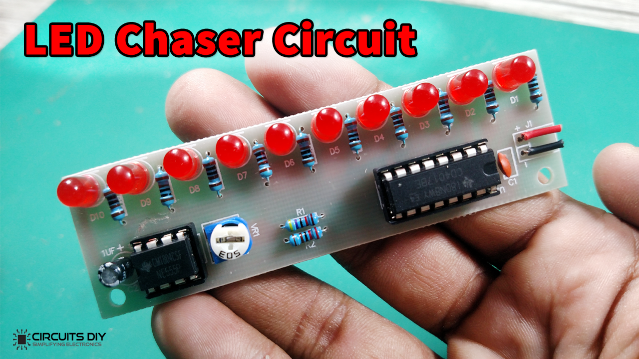
The LED Chaser Circuit is basically a serial switch of LEDs in a continuous manner. ie In a short duration of time they are being switched & resulting in the formation of a chasing pattern.
In this tutorial, we are going to make a “Simple LED Chaser Circuit that can be made using a 555 timer and CD4017 decade counter IC. You can use this circuit for decorative purposes. By modifying the circuit in a proper way, you can even use this to control lights working on AC mains.

Hardware Components
The following components are required to make LED Chaser Circuit
| S.No | Component | Value | Qty |
|---|---|---|---|
| 1. | Breadboard | – | 1 |
| 2. | Connecting Wires | – | 1 |
| 3. | Battery | 9v | 1 |
| 4. | Decade Counter IC | CD4017 | 1 |
| 5. | IC | NE555 Timer | 1 |
| 6. | Resistor | 47k, 1k | 1, 10 |
| 7. | Variable Resistor | 50k | 1 |
| 8. | Electrolytic Capacitor | 1uf | 1 |
| 9. | Ceramic Capacitor | 10nF | 1 |
| 10 | LED | 5mm | 11 |
555 IC Pinout

For a detailed description of pinout, dimension features, and specifications download the datasheet of 555 Timer
CD4017 Pinout
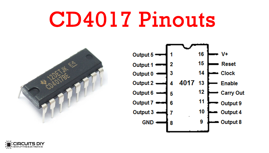
For a detailed description of pinout, dimension features, and specifications download the datasheet of CD4017
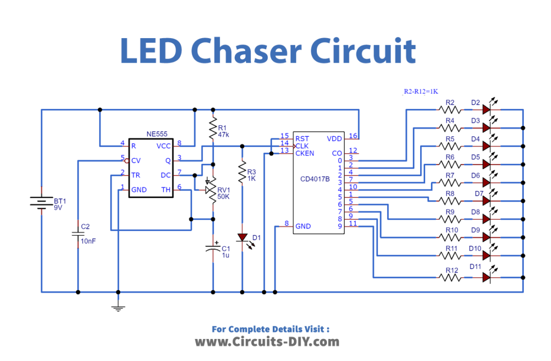
LED Chaser Circuit
Useful Steps
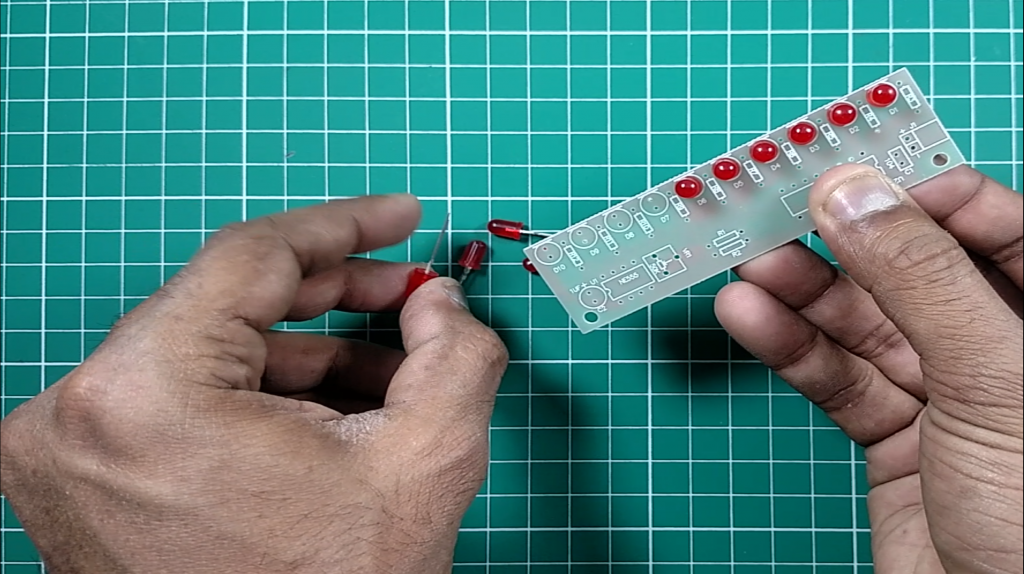
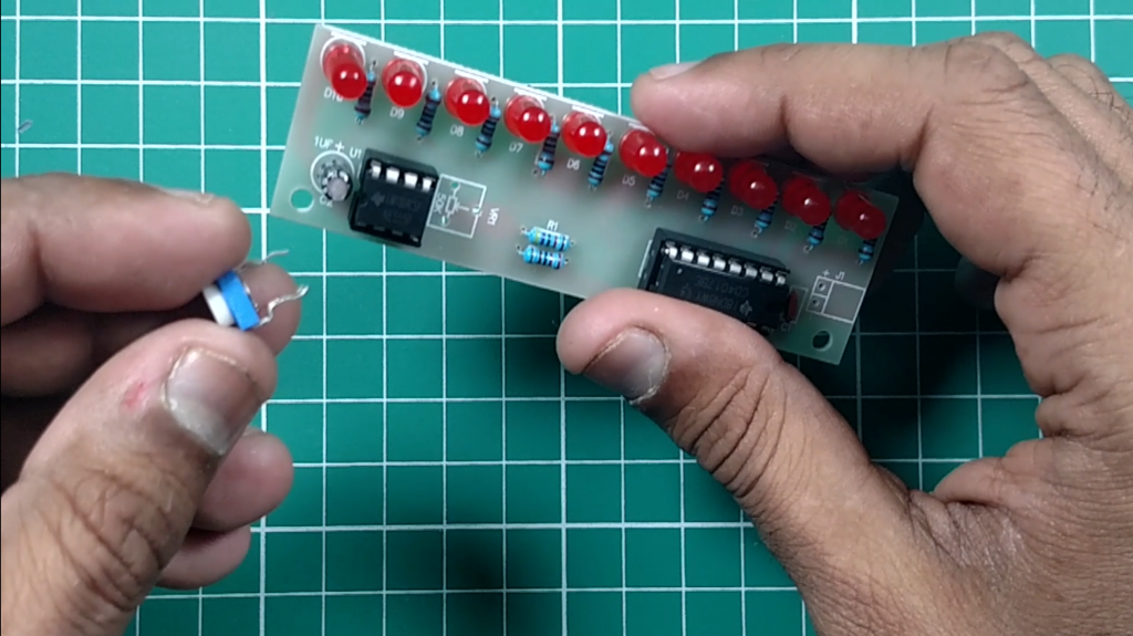
Step 1 Solder All LEDs
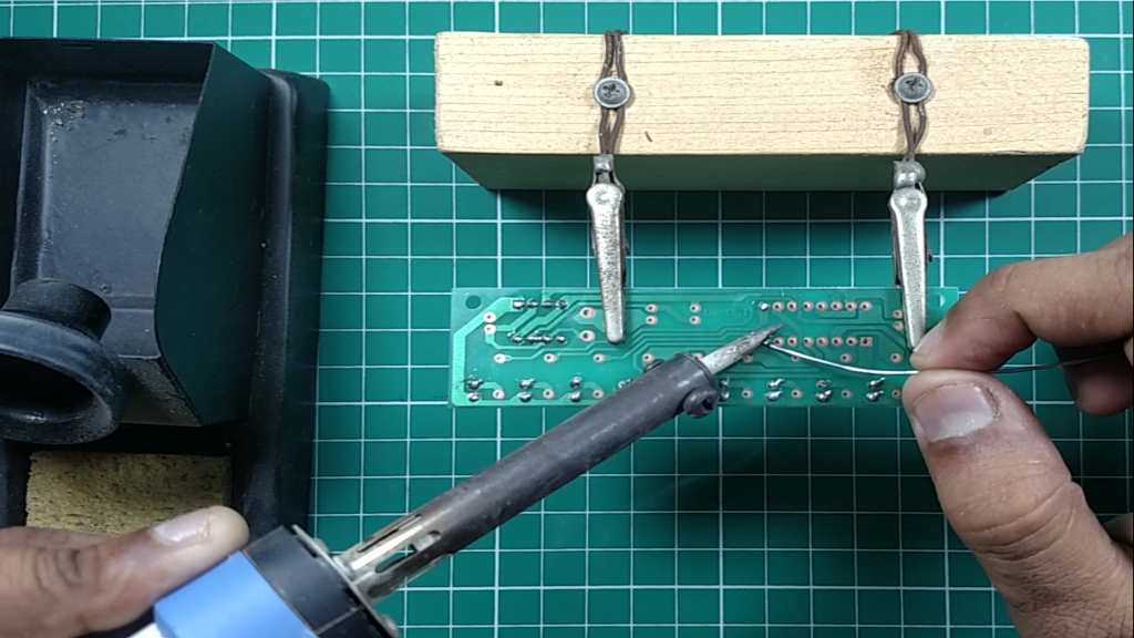
Step 2 Solder Base of both ICs
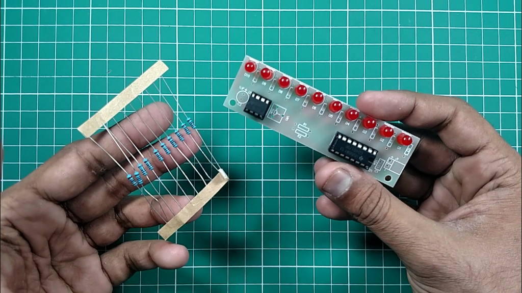
Step 3 Solder All Resistors
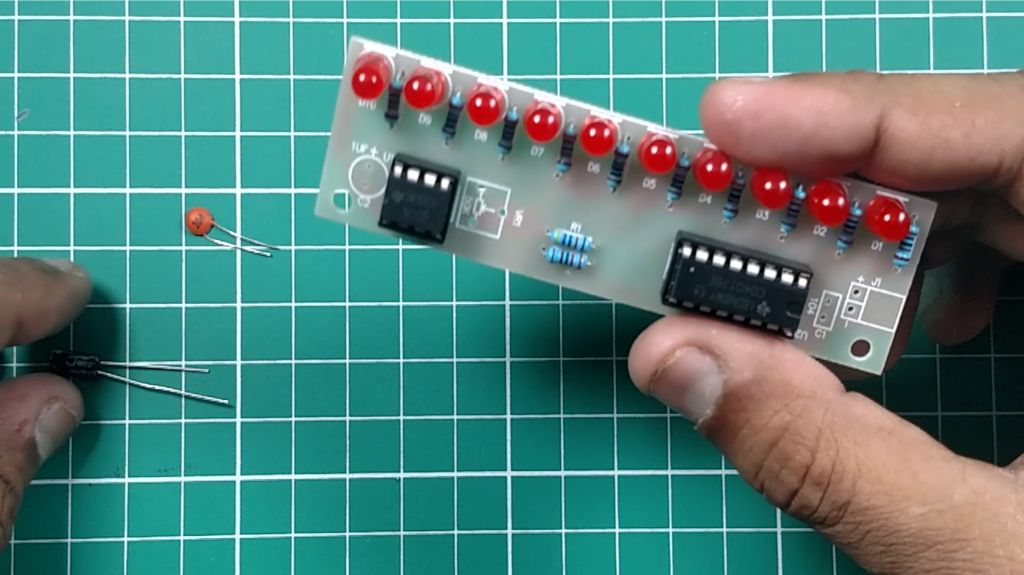
Step 4 Solder Both Capacitors
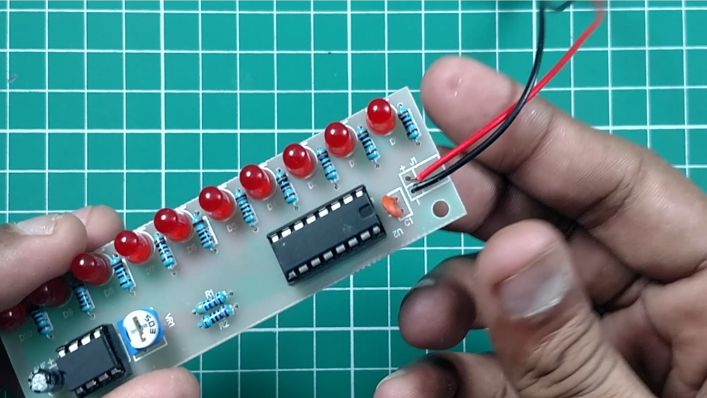
Step 5 Solder Variable Resistor
Step 6 Solder Power Connector
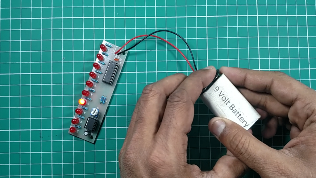
Step 7 Let’s Power up the Circuit
Working Explanation
As you can see in the circuit diagram above a 555 Timer is wired in Astable Multivibrator mode and its output is connected to the 4017 counter IC. The output frequency of the 555 timers is determined by R1, VR & C1.
We have used IC NE555 because we need perfect timing for the serial switching of LEDs. This circuit also needs a counting system that can be fulfilled by a counting IC which is CD4017 this will provide a fast switching to the circuit. To avoid high-frequency noise in the 555 timers we add a ceramic capacitor to control the voltage (CV – 5th Pin) of the 555 timer
In Decade Counter 4017 GND (16th pin) and VCC (8th pin) of the CD4017 IC are connected directly to the power supply. The clock enable (13th pin) is an active low input, so it is connected to the ground. Each decoded output pin (Q0 ~ Q9) is connected to the LED with current limiting resistors (R2-R11).