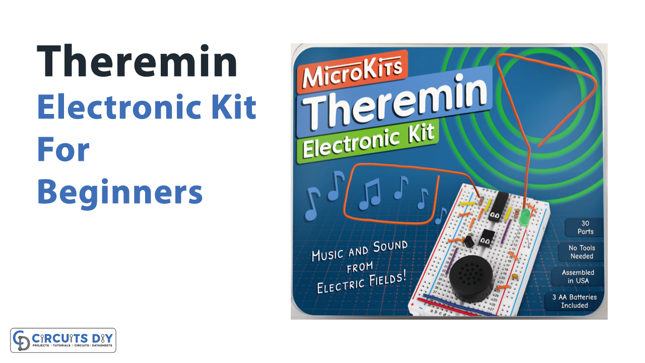
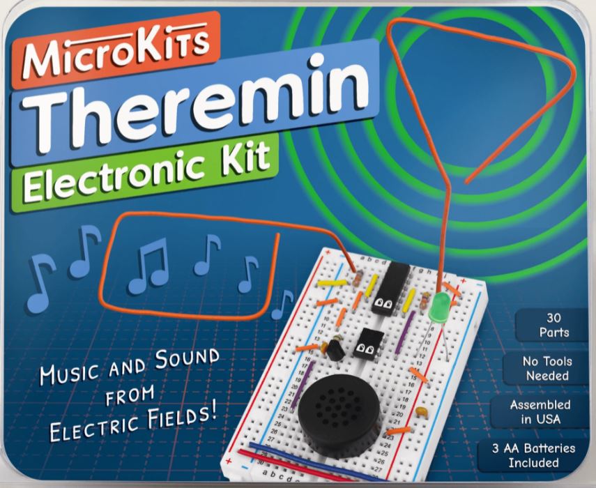
MicroKits Theremin Electronic kit is a great DIY project for people with any level of electronics knowledge, it provides fun & easy project that can be practiced by people of any age regardless of their experience with electronic devices & circuits. In this article, we are going to go over the key features & step-by-step construction of a theremin device using the MicroKits Theremin Electronic Kit.
What’s a Theremin Circuit?
A theremin circuit creates music and sound at a distance, without touch Moving your hand towards the right antenna plays higher pitched notes, and moving towards the left antenna decreases volume In 1920, an engineer named Leon Theremin invented this instrument Since then, it’s been used to create experimental music and eerie sound effects and inspired many electronic musical instruments.
For Further Information please visit: www.MicroKits.net
What’s in the Kit?
The MicroKits Theremin Electronic Kit consists of the following parts.
| S.no | Component | Value | Qty |
|---|---|---|---|
| 1. | Microprocessor IC | – | 1 |
| 2. | Oscillator IC | NE556 | 1 |
| 3. | Transistor NPN | – | 1 |
| 4. | Speaker | 8Ω | 1 |
| 5. | LED | 5mm/Green | 1 |
| 6. | Enameled Copper Antennas | – | 2 |
| 7. | Ceramic Capacitor | 100nF | 2 |
| 8. | Resistor | 560Ω, 47KΩ, 68KΩ | 3 |
| 9. | Breadboard | – | 1 |
| 10. | Batteries | AA | 3 |
| 11. | Connecting Wires | – | 15 |
Electronic Theremin Circuit
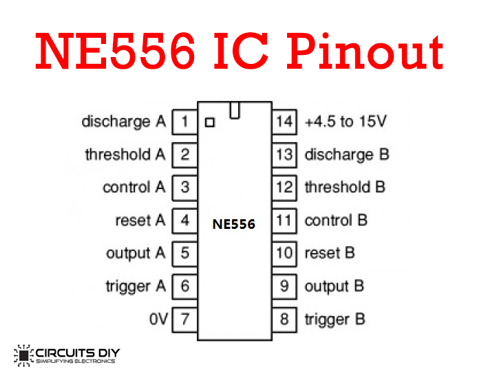
For a detailed description of pinout, dimension features, and specifications download the datasheet of NE556
Theremin Kit Assembly
The Kit Assembly is very simple & can be broken down into the following stages:
Stage 1: Power & LED
- Place the board with Row 1 on top.
- Place the MCU (Micro) IC in rows 11 to 14 & columns E & F. Make sure the notch is pointed in the correct direction (the eyes must be pointed downwards).
- Place a capacitor between -ve & +ve power rails as shown in the circuit diagram.
- Connect Orange Wire From A14 to the -ve power rail.
- Orange wire from J14 to +ve power rail.
- Place a red wire from left +ve power rail to right +ve power rail.
- Place a Blue wire from left -ve power rail to right -ve power rail.
- The LED has a positive & negative side. connect the longer positive wire to J12, and the shorter negative wire to -ve power rail.
- Find the switch on the battery holder, For now, set it to OFF.
- Open the battery holder & install three new AA Batteries. Check inside the battery holder to see the correct way to install the batteries.
- Plug the Battery holder’s red wire into the +ve rail & the black wire into the -ve power rail, as shown.
Stage 2: Audio
- Turn power “OFF” while building.
- Place a capacitor from B14 to B15
- Find the green, blue, and brown colored 560 Ohm resistor & place it from C12 to C15.
- Connect Purple wire from A16 to A23
- Orange wire from J23 to the +ve rail.
- Place the transistor in D14, D15 & D16 with the flat side to the left.
- The speaker has two pins. Place them in E23 & G23.
- Double-check your work, then turn the power ‘ON’!
- If you hear nothing, turn it ‘OFF’ & troubleshoot for mistakes.
- If you hear a constant tone, your speaker system is working!
Stage 3: Pitch Antenna
- Turn power ‘OFF’ while building the circuit.
- Place the oscillator IC (Tick) in rows 1 to 7 & columns E & F, with the notch pointed upwards (eyes pointed downwards).
- Connect an orange wire from J1 to +ve power rail.
- Connect an orange wire from J5 to +ve power rail.
- Now Connect an orange wire from A7 to the -ve power rail.
- Connect the yellow wire from G3 to G7.
- Connect Purple wire from H6 to H13
- Find the yellow Violet Orange colored 47K Ohm resistor & place it from I3 to I6.
- Place one of the antennas in J3. If it’s hard to place in the hole, try to wiggle it into place. It should stick straight up & away from the board. Bend it however you want. this is the pitch antenna
- When ready, turn power “ON”! what happens when you reach towards the antenna?
- If the note stays constant, turn it “OFF” & Troubleshoot like before.
- If the pitch increases as your hand approaches, congratulations! you have made a working theremin device!
Stage 4: Volume Antenna
- Find the Blue Gray Orange colored 58K Ohm resistor & place it from B2 to B5.
- Connect yellow wire from A4 to +ve power rail.
- Now Connect yellow wire from D2 to D6.
- Connect Orange wire from C5 to C8.
- Connect Orange wire from B8 to B11.
- Place the second antenna in A2. If it’s hard to place in the hole, try to wiggle it into place. The wire should stick straight up & away from the board and the other antenna. Bend it however you want. this is the volume antenna.
- Turn power”ON”! What happens when you reach the antenna?
- If the volume decreases as your hand approaches the volume antenna, congratulations! you have successfully completed your theremin circuit!
Working Principle
A Theremin circuit works on the principle of sensing capacitance, or how easy it is to store energy between objects in an electric field. By moving your hands closer to the antenna, you increase the capacitance. The closer two things (the hand & the antenna) are the more electric fields build up between them. On moving your hand away, the distance will weaken the electric fields and decrease the capacitance.
Tips & Best Usage Practices
- Use your left hand for the volume antenna, and right for pitch
- Move your whole hand towards the instrument and focus on the middle of the antenna, not the end.
- Bend the antennas away from each other, so they don’t interfere.
- Your theremin automatically tunes itself. If the tuning seems wrong, just turn it off and on again.
- Turn the battery “OFF” when not in use.
- If your theremin acts unstable, try replacing the batteries. Only replace batteries with matching new alkaline AA batteries
All in all, MicroKits Theremin Electronic Kit is a great, easy & fun way of introducing beginner students & hobbyists to the field of electronics.