
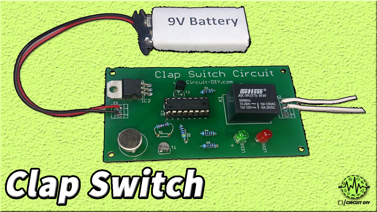
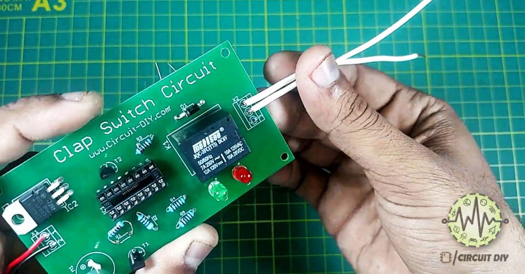
Clap switch circuits are an important part of today’s home automation control circuitry, as it ventures into the domain of dynamic control of home appliances using a simple sound signal. So, Today in this tutorial, we are going to make a “Clap Switch Circuit using CD4017 Counter IC“.
The heart of this DIY Circuit is a CD4017 counter IC. A CD4017 IC is a 16-pin CMOS decade counter/Divider with 10 outputs. It is also known as the ‘Johnson 10 stage decade counter’. It has 10 decoded outputs that give output signals one by one in sequence when a clock signal from the clock input is given.
Hardware Components
The following components are required to make Clap Switch Circuit
| S.No | Component | Value | Qty |
|---|---|---|---|
| 1) | IC | CD4017 | 1 |
| 2) | Regulator IC | LM7805 | 1 |
| 3) | SPDT Relay | 5V/9V | 1 |
| 4) | Condenser Mic | – | 1 |
| 5) | IC Jacket | 16 pin | 1 |
| 6) | NPN Transistor | BC547 | 2 |
| 7) | LEDs | 5mm | 2 |
| 8) | AC Bulb/Lamp | 220V | 1 |
| 9) | Resistors | 22K, 1K, 470 Ohms | 1, 3, 1 |
| 10) | Soldering Iron | 45W – 60W | 1 |
| 11) | Soldering Flux | – | 1 |
| 12) | DC Battery | 9V | 1 |
CD4017 Pinout
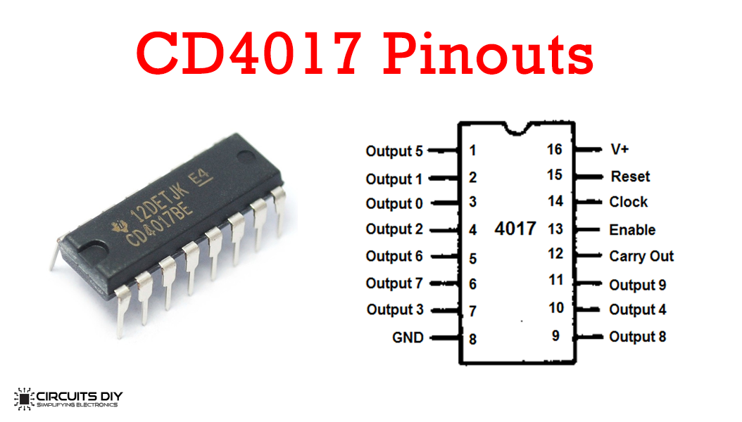
For a detailed description of pinout, dimension features, and specifications download the datasheet of CD4017 IC
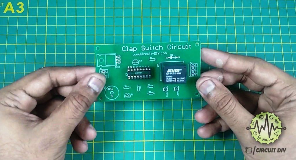
Useful Steps
Follow all steps carefully from the video tutorial.
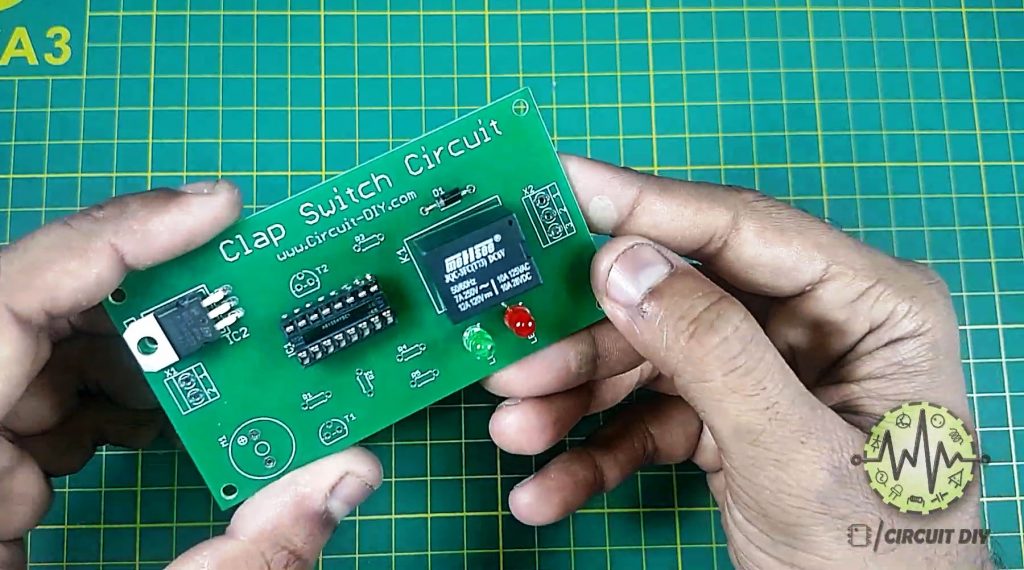
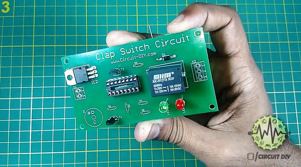
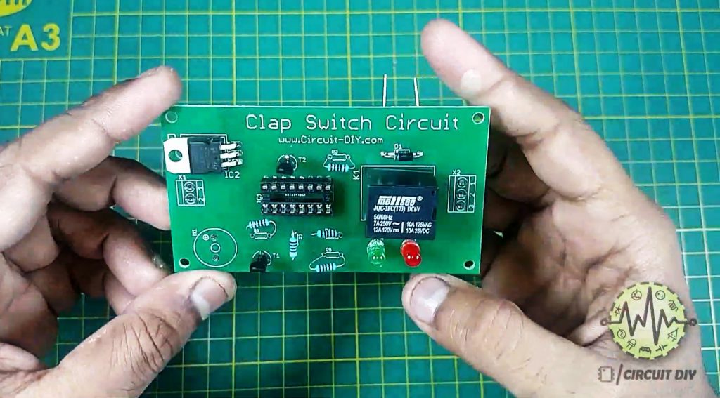
1) Take the 5V SPDT Relay & solder it onto the PCB board

2) Solder the 16-pin IC jacket for CD4017 on the PCB Board
3) Solder the LM7805 voltage regulator on the PCB Board

4) Connect the LEDs and the 1N4007 diode on the PCB Board
5) Solder the BC547 Transistors onto the PCB Board
6) Solder Resistors (R1, R2, R3, R4, R5)
7) Solder the Electret mic on the PCB Board.
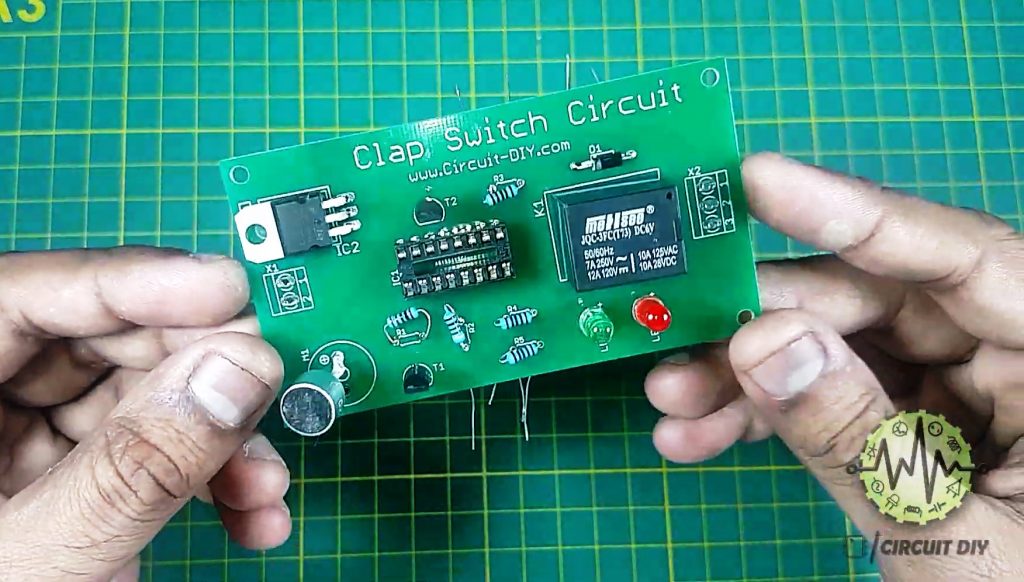
8) Solder Input (Battery Clips) & Output Connectors to the PCB Board
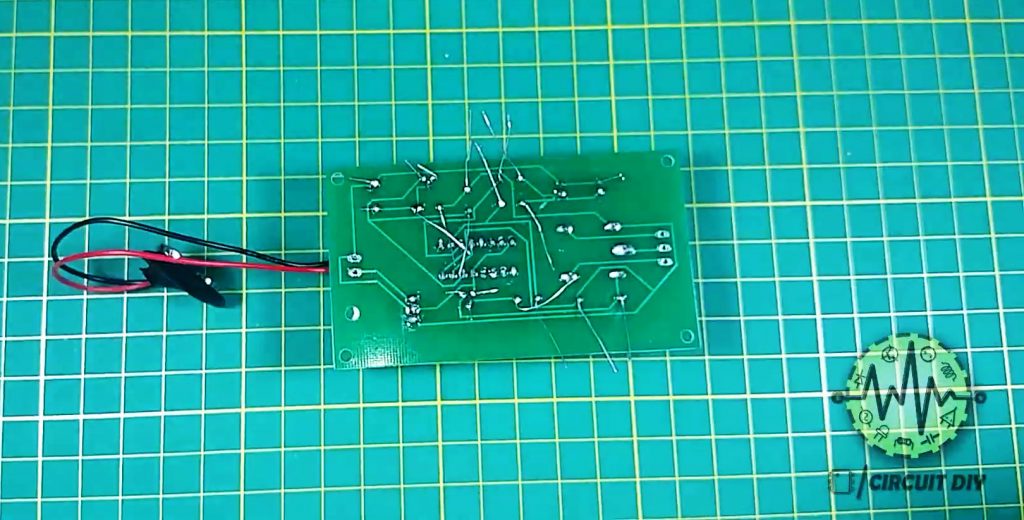
9) Cut any extra wiring using a wire cutter.

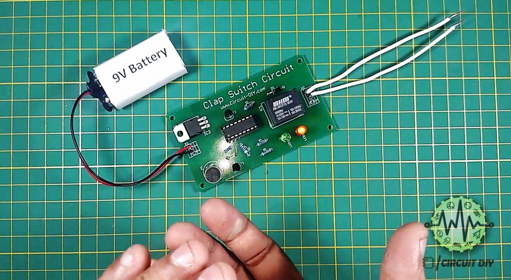
10) Connect the CD4107 IC & 9V battery, then power up the circuit

11) Testing & Inspection.
Circuit Diagram
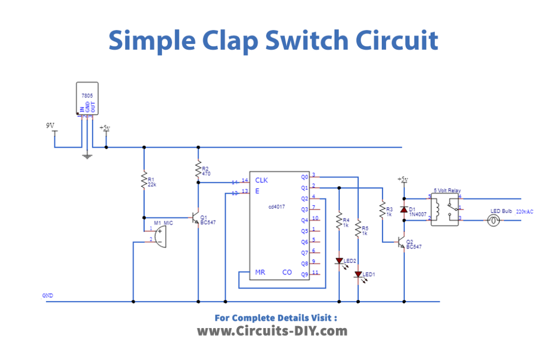
Working Explanation
The main component of this circuit is a CD4017 decade counter. An audio signal received by a device such as a mic serves as the input to the circuit. This input AC audio signal functions as a control signal to the base of a BC547 transistor
The output from the collector of the BC547 provides a clock input to PIN 14 of the counter IC, subsequently triggering output pins Q0, Q1 & Q2 of the IC. Then, the output from the IC acts as a control signal to the base of the second BC547 NPN transistor & triggers LEDs 1 & 2. The output from the 2nd transistor energizes the coil of the 5V SPDT relay. This engages the relay & completes the circuit for an external output device such as a 220V lamp bulb. Here, we have used a diode (1N4007) to protect the SPDT relay from negative feedback in case of a short. Always use appropriately rated SPDT relays with respect to the input supply voltage.
Applications
- You can also use it to control small devices such as switches & motors.
- Control AC Appliances by just clapping by hand.
Related posts:
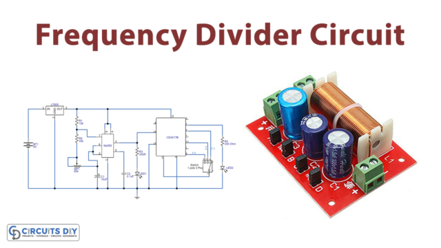 Frequency Divider Circuit
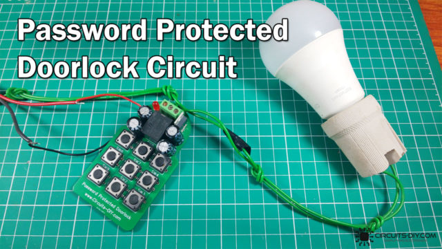 Password Protected Door Lock Circuit - DIY
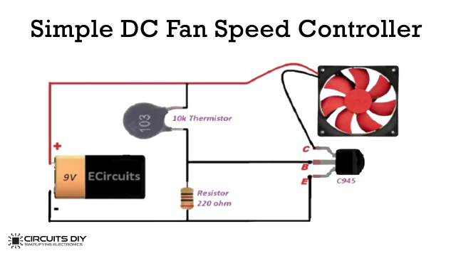 How to control the speed of a DC Fan - Electronics Projects
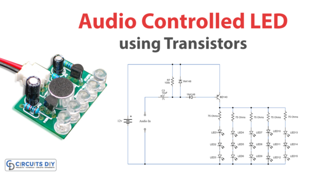 Audio Controlled LED Circuit using Transistors - DIY
 Simple Clap Switch Circuit using NE555 Precision Timer IC
 Circular LED Chaser using 555 timer & CD4017 - Electronics Projects


