Introduction
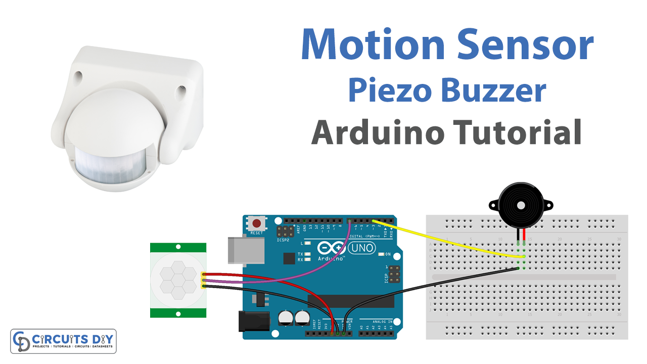
In this tutorial, we will show you how to connect the HC-SR501 PIR motion sensor and the 5V piezoelectric buzzer to the Arduino UNO microcontroller, write a code that detects motion and triggers the buzzer, and use the serial monitor to display the status of the sensor. By the end of this tutorial, you will have a working motion-activated buzzer that you can customize to suit your needs.
The HC-SR501 PIR motion sensor is a pyroelectric infrared sensor that can detect the presence of human or animal movement within a certain range. It’s a low-cost and widely used sensor that can be easily integrated into a variety of projects. The 5V piezoelectric buzzer, on the other hand, is a simple but powerful audio output device that can generate different tones depending on the input signal.
Hardware Components
You will require the following hardware for Motion Sensor Piezo Buzzer with Arduino.
| S.no | Component | Value | Qty |
|---|---|---|---|
| 1. | Arduino UNO | – | 1 |
| 2. | USB Cable Type A to B | – | 1 |
| 3. | Motion Sensor | HC-SR501 | 1 |
| 4. | Piezo Buzzer | – | 1 |
| 5. | Power Adapter for Arduino | 9V | 1 |
| 6. | Breadboard | – | 1 |
| 7. | Jumper Wires | – | 1 |
Motion Sensor with Arduino
- Connect the HC-SR501 PIR motion sensor to your Arduino UNO. The Vcc pin should be connected to 5V, the GND pin should be connected to GND, and the OUT pin should be connected to digital pin 2 on your Arduino UNO.
- Connect the 5V piezoelectric buzzer to your Arduino UNO. The positive pin should be connected to digital pin 3, and the negative pin should be connected to GND.
- In the Arduino IDE, import the necessary libraries by adding these lines at the top of your sketch:
#include <SoftwareSerial.h>
- In the setup() function, configure the digital input pin connected to the PIR sensor as an input and the digital output pin connected to the buzzer as an output. Also, initialize the serial monitor with a baud rate of your choice:
pinMode(2, INPUT);
pinMode(3, OUTPUT);
Serial.begin(9600);
- In the loop() function, read the state of the PIR sensor using the digitalRead() function. If the PIR sensor detects motion, turn on the buzzer using the digitalWrite() function and send a message to the serial monitor indicating that motion has been detected:
int motion = digitalRead(2);
if(motion == HIGH){
  digitalWrite(3, HIGH);
  Serial.println("Motion detected!");
}
- If the PIR sensor does not detect motion, turn off the buzzer and send a message to the serial monitor indicating that there is no motion:
else{
  digitalWrite(3, LOW);
  Serial.println("No motion detected.");
}
- Upload the code to your Arduino UNO and open the serial monitor to see the status of the PIR sensor.
Schematic
Make connections according to the circuit diagram given below.
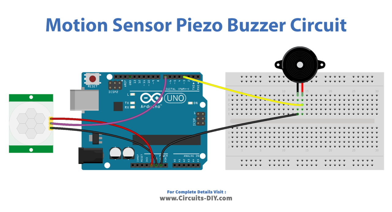
Wiring / Connections
| Arduino | PIR Sensor |
|---|---|
| 5V | VCC |
| GND | GND |
| D7 | SIG |
Installing Arduino IDE
First, you need to install Arduino IDE Software from its official website Arduino. Here is a simple step-by-step guide on “How to install Arduino IDE“.
Code
Now copy the following code and upload it to Arduino IDE Software.
const int MOTION_SENSOR_PIN = 7;   // Arduino pin connected to the OUTPUT pin of motion sensor
const int BUZZER_PIN        = 3;   // Arduino pin connected to Buzzer's pin
int motionStateCurrent      = LOW; // current  state of motion sensor's pin
int motionStatePrevious     = LOW; // previous state of motion sensor's pin

void setup() {
  Serial.begin(9600);                // initialize serial
  pinMode(MOTION_SENSOR_PIN, INPUT); // set arduino pin to input mode
  pinMode(BUZZER_PIN, OUTPUT);          // set arduino pin to output mode
}

void loop() {
  motionStatePrevious = motionStateCurrent;            // store old state
  motionStateCurrent  = digitalRead(MOTION_SENSOR_PIN); // read new state

  if (motionStatePrevious == LOW && motionStateCurrent == HIGH) { // pin state change: LOW -> HIGH
    Serial.println("Motion detected!");
    digitalWrite(BUZZER_PIN, HIGH); // turn on
  }
  else
  if (motionStatePrevious == HIGH && motionStateCurrent == LOW) { // pin state change: HIGH -> LOW
    Serial.println("Motion stopped!");
    digitalWrite(BUZZER_PIN, LOW);  // turn off
  }
}
Working Explanation
In the setup() function, the digital input pin connected to the PIR sensor is configured as an input using the pinMode() function, and the digital output pin connected to the buzzer is configured as an output. The serial monitor is also initialized with a baud rate of your choice using the Serial.begin() function.
In the loop() function, the digitalRead() function is used to read the state of the PIR sensor and store it in a variable. If the sensor detects motion, the digitalWrite() function is used to turn on the buzzer and send a message to the serial monitor indicating that motion has been detected. If the sensor does not detect motion, the buzzer is turned off and a message is sent to the serial monitor indicating that there is no motion.
Applications
- Security Alarm
- Automated Lighting
- Automated Doors and Gates
- Interactive Exhibits and Displays
- Robotics and Automation
- Smart Home
Conclusion.
We hope you have found this Motion Sensor Piezo Buzzer Circuit very useful. If you feel any difficulty in making it feel free to ask anything in the comment section.