Introduction
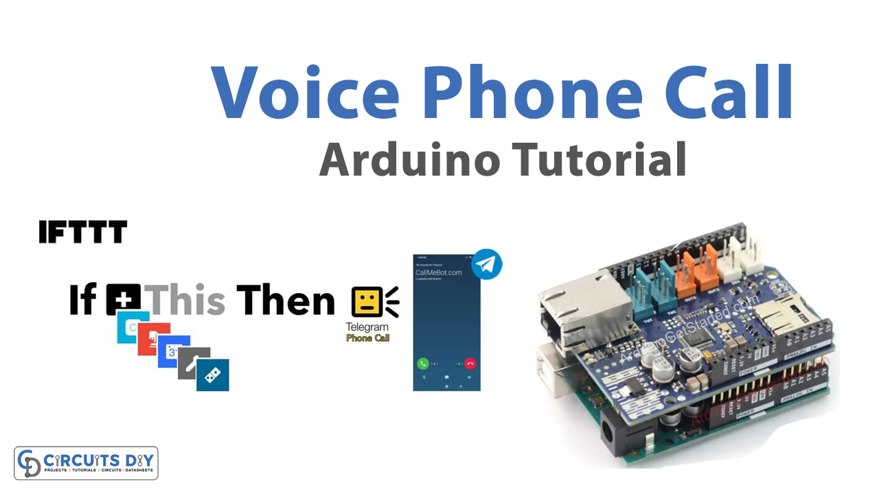
With the increasing popularity of Internet of Things (IoT) devices, the ability to remotely control and monitor electronic systems has become an essential requirement for many applications. One such application is the ability to make VoIP phone calls, which can be useful for security alerts, emergency notifications, and other similar purposes. While there are many commercial solutions available for making VoIP phone calls, these can be expensive and may not always fit specific requirements. Fortunately, with the combination of an Arduino UNO microcontroller, a Velleman KA04 Ethernet Shield for Arduino, and the IFTTT webhooks applet, it is possible to create a cost-effective and customizable VoIP phone system that can be integrated with other IoT devices.
VoIP stands for Voice over Internet Protocol, which refers to a technology that allows voice communication to be transmitted over the Internet instead of traditional phone lines. VoIP converts analog voice signals into digital packets that can be sent over the Internet using an IP network, such as a LAN, WAN, or the Internet. VoIP technology is widely used for voice communication because it offers several advantages over traditional phone systems, including lower costs, better scalability, and flexibility.
Hardware Components
You will require the following hardware for Voice Phone Calls with Arduino.
| S.no | Component | Value | Qty |
|---|---|---|---|
| 1. | Arduino UNO | – | 1 |
| 2. | USB Cable Type A to B | – | 1 |
| 3. | Arduino Ethernet Shield 2 | – | 1 |
| 4. | Ethernet Cable | – | 1 |
| 5. | Power Adapter for Arduino | 9V | 1 |
Make Voice Phone Call with Arduino
Step 1: Connect the Ethernet Shield to your Arduino UNO. Use the following pin connections:
- Ethernet Shield pin 10 to Arduino UNO pin 10
- Ethernet Shield pin 11 to Arduino UNO pin 11
- Ethernet Shield pin 12 to Arduino UNO pin 12
- Ethernet Shield pin 13 to Arduino UNO pin 13
Step 2: Include the necessary libraries in your code:
#include <Ethernet.h>
#include <SPI.h>
Step 3: Define the Ethernet Shield pins:
#define ETH_CS 10
#define ETH_MOSI 11
#define ETH_MISO 12
#define ETH_SCK 13
Step 4: Initialize the Ethernet Shield:
byte mac[] = { 0xDE, 0xAD, 0xBE, 0xEF, 0xFE, 0xED };
IPAddress ip(192, 168, 1, 177);
EthernetClient client;

void setup() {
  Ethernet.begin(mac, ip);
}
Step 5: Create a function to make the VoIP phone call:
void makeCall(String phoneNumber) {
  client.print("POST /trigger/make_call/with/key/{YOUR_KEY} HTTP/1.1\r\n");
  client.print("Host: maker.ifttt.com\r\n");
  client.print("Content-Type: application/json\r\n");
  client.print("Content-Length: ");
  client.print(phoneNumber.length() + 8);
  client.print("\r\n\r\n");
  client.print("{\"value1\":\"");
  client.print(phoneNumber);
  client.print("\"}");
}
Step 6: Use the function to make a VoIP phone call and print the status on the serial monitor:
void loop() {
  if (client.connect("maker.ifttt.com", 80)) {
    makeCall("1234567890");
    Serial.println("VoIP phone call initiated.");
    client.stop();
  } else {
    Serial.println("Connection failed.");
  }
  delay(5000);
}
In this example, the code uses the IFTTT webhooks applet to initiate the VoIP phone call to the number “1234567890”. The status of the phone call is printed on the serial monitor. You can modify the phone number and the IFTTT webhook applet URL as per your requirements.
Installing Arduino IDE
First, you need to install Arduino IDE Software from its official website Arduino. Here is a simple step-by-step guide on “How to install Arduino IDE“.
Installing Libraries
Before you start uploading a code, download and unzip the following libraries at /Progam Files(x86)/Arduino/Libraries (default), in order to use the sensor with the Arduino board. Here is a simple step-by-step guide on “How to Add Libraries in Arduino IDE“.
Code
Now copy the following code and upload it to Arduino IDE Software.
#include <Ethernet.h>
#include <SPI.h>
#define ETH_CS 10
#define ETH_MOSI 11
#define ETH_MISO 12
#define ETH_SCK 13
byte mac[] = { 0xDE, 0xAD, 0xBE, 0xEF, 0xFE, 0xED };
IPAddress ip(192, 168, 1, 177);
EthernetClient client;

void setup() {
  Ethernet.begin(mac, ip);
}
void makeCall(String phoneNumber) {
  client.print("POST /trigger/make_call/with/key/{YOUR_KEY} HTTP/1.1\r\n");
  client.print("Host: maker.ifttt.com\r\n");
  client.print("Content-Type: application/json\r\n");
  client.print("Content-Length: ");
  client.print(phoneNumber.length() + 8);
  client.print("\r\n\r\n");
  client.print("{\"value1\":\"");
  client.print(phoneNumber);
  client.print("\"}");
}
void loop() {
  if (client.connect("maker.ifttt.com", 80)) {
    makeCall("1234567890");
    Serial.println("VoIP phone call initiated.");
    client.stop();
  } else {
    Serial.println("Connection failed.");
  }
  delay(5000);
}
Working Explanation
The sketch defines the Ethernet pins used for communication, as well as the MAC address and IP address for the Ethernet module. It also sets up an Ethernet client and initializes serial communication. The makeCall() function takes a phone number as a parameter and sends an HTTP POST request to IFTTT’s Maker service, passing the phone number as a value in a JSON payload. The HTTP request includes the API key for the Maker service, the content type, and the content length.
The loop() function attempts to connect to the Maker service using the Ethernet client. If the connection is successful, it calls the makeCall() function with a test phone number, prints a message to the serial port, and stops the client connection. If the connection fails, it prints an error message to the serial port. The loop() function then waits for 5 seconds before attempting to connect again.
Applications
- Security alerts
- Emergency notifications
- Remote control of devices
- Home automation
- Custom applications
Conclusion.
We hope you have found this Voice Phone Call Circuit very useful. If you feel any difficulty in making it feel free to ask anything in the comment section.