Introduction
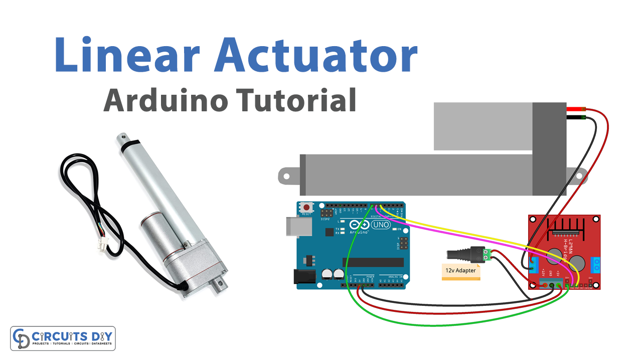
Controlling a linear actuator with an Arduino microcontroller is a simple and efficient way to automate various tasks that require precise linear motion. A linear actuator is a device that converts rotary motion into linear motion, and it’s often used in robotics, automation, and other projects that require precise movement. In this tutorial, we will show you how to interface a 12V DC linear actuator with an L298N Arduino motor driver module and an Arduino UNO microcontroller.
The Progressive Automations Micro Linear Electric Actuator 12V is a small and compact linear actuator that runs on 12V DC power. It is designed to be used in tight spaces and has a stroke length of up to 100mm (4 inches) and a force of up to 2200N (500lbs). It can be controlled by a variety of controllers such as microcontrollers and PLCs. It can be used for various applications such as industrial automation, medical equipment, and laboratory automation. This actuator is built with high-quality materials which makes it durable and long-lasting.
Hardware Components
You will require the following hardware for Interfacing Linear Actuator with Arduino.
| S.no | Component | Value | Qty |
|---|---|---|---|
| 1. | Arduino UNO | – | 1 |
| 2. | USB Cable Type A to B | – | 1 |
| 3. | Linear Actuator | – | 1 |
| 4. | Motor Driver Module | – | 1 |
| 5. | 12V Power Adapter | – | 1 |
| 6. | DC Power Jack | – | 1 |
| 7. | 9V Power Adapter for Arduino | – | 1 |
| 8. | Jumper Wires | – | 1 |
Linear Actuator with Arduino
- Connect the 12V DC linear actuator to the L298N motor driver module according to the module’s pinout diagram. Typically, this will involve connecting the actuator’s positive and negative terminals to the module’s “IN1” and “IN2” terminals, respectively.
- Connect the L298N motor driver module to the Arduino UNO microcontroller. This will typically involve connecting the module’s “EN” pin to a PWM-enabled digital pin on the Arduino (e.g. pin 3), and connecting the “IN1” and “IN2” pins to digital pins on the Arduino (e.g. pin 4 and 5).
- Open the Arduino IDE and create a new sketch.
- Define the pin numbers for the motor driver module and linear actuator in the sketch’s setup() function. For example:
#define enPin 3
#define in1Pin 4
#define in2Pin 5
- In the setup() function, initialize the defined pin numbers as outputs using the pinMode() function. For example:
void setup(){
    pinMode(enPin, OUTPUT);
    pinMode(in1Pin, OUTPUT);
    pinMode(in2Pin, OUTPUT);
}
- In the loop() function, use the digitalWrite() function to write a HIGH signal to the “IN1” pin, and a LOW signal to the “IN2” pin and “EN” pin to turn the actuator on.
digitalWrite(in1Pin, HIGH);
digitalWrite(in2Pin, LOW);
digitalWrite(enPin, HIGH);
- If you want to turn off the linear actuator, use the digitalWrite() function to write a LOW signal to the “IN1” pin, “IN2” pin and “EN” pin.
digitalWrite(in1Pin, LOW);
digitalWrite(in2Pin, LOW);
digitalWrite(enPin, LOW);
- If you want to see the status of the linear actuator, you can use the Serial.print() function to post the status of the linear actuator on the serial monitor.
Serial.println("Linear Actuator is On");
or
Serial.println("Linear Actuator is OFF");
Schematic
Make connections according to the circuit diagram given below.
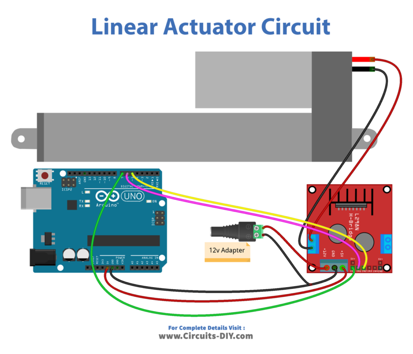
Wiring / Connections
| Arduino | LN298N |
|---|---|
| 5V | 5V |
| GND | GND |
| D7 | ENABLE 1 |
| D6 | INP 1 |
| D5 | INP2 |
Installing Arduino IDE
First, you need to install Arduino IDE Software from its official website Arduino. Here is a simple step-by-step guide on “How to install Arduino IDE“.
Code
Now copy the following code and upload it to Arduino IDE Software.
const int ENA_PIN = 7; // the Arduino pin connected to the EN1 pin L298N
const int IN1_PIN = 6; // the Arduino pin connected to the IN1 pin L298N
const int IN2_PIN = 5; // the Arduino pin connected to the IN2 pin L298N

// the setup function runs once when you press reset or power the board
void setup() {
  // initialize digital pins as outputs.
  pinMode(ENA_PIN, OUTPUT);
  pinMode(IN1_PIN, OUTPUT);
  pinMode(IN2_PIN, OUTPUT);

  digitalWrite(ENA_PIN, HIGH);
}

// the loop function runs over and over again forever
void loop() {
  // extend the actuator
  digitalWrite(IN1_PIN, HIGH);
  digitalWrite(IN2_PIN, LOW);

  delay(20000); // actuator will stop extending automatically when reaching the limit

  // retracts the actuator
  digitalWrite(IN1_PIN, LOW);
  digitalWrite(IN2_PIN, HIGH);

  delay(20000); // actuator will stop retracting automatically when reaching the limit
}
Working Explanation
The setup() function is used to set the pin modes for the digital pins that will be used to control the movement of the linear actuator and to establish communication with the serial monitor.
the loop() functions include instructions to check the status of the digital pins used to control the movement of the linear actuator and send the appropriate commands to the L298N motor driver module to move the actuator accordingly. It may also include instructions to read the position of the actuator and send this information to the serial monitor for monitoring and tracking.
Applications
- Robotics
- Automation
- Industrial control
- Home automation
- Medical equipment
- Research and Development
- Educational projects
- DIY projects
Conclusion
We hope you have found this Linear Actuator Circuit very useful. If you feel any difficulty in making it feel free to ask anything in the comment section.