Introduction
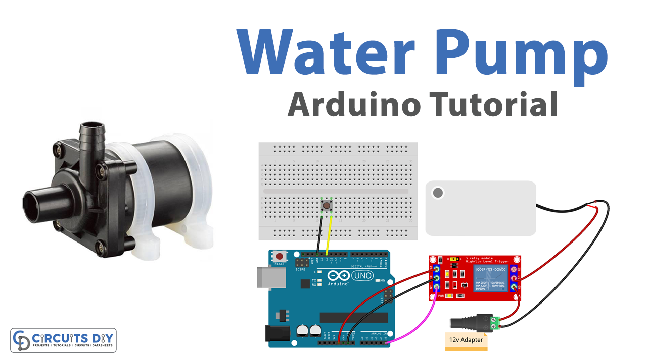
A pushbutton-controlled 5V SPDT relay to control a DC water pump is a system that uses a relay to turn a DC water pump on and off. The relay is controlled by a pushbutton, which when pressed, sends a signal to the relay to either close or open the circuit, turning the pump on or off. The system typically uses a 5V SPDT (single pole, double throw) relay, which is a type of relay that has one common terminal and two normally open and normally closed terminals. When the pushbutton is pressed, it sends a signal to the relay, which then switches the common terminal from one of the normally open or normally closed terminals to the other, turning the pump on or off.
A 12V DC water pump is an electric pump that is powered by a 12-volt direct current (DC) power source and is designed to pump water. These pumps are commonly used in a variety of applications such as water transfer, irrigation systems, rainwater harvesting systems, etc. These pumps typically have a low power consumption and are efficient and can be powered by a variety of power sources such as batteries, solar panels, or a 12V DC power supply.
Hardware Components
You will require the following hardware for Water Pump Arduino Circuit.
| S.no | Component | Value | Qty |
|---|---|---|---|
| 1. | Arduino UNO | – | 1 |
| 2. | USB Cable Type A to B | – | 1 |
| 3. | Button | – | 1 |
| 4. | Relay | – | 1 |
| 5. | Pump | 12V | 1 |
| 6. | Vinyl Tube | – | 1 |
| 7. | DC Power Jack | – | 1 |
| 8. | Power Adapter for Arduino | 9V | 1 |
| 9. | Power Adapter | 12V | 1 |
| 10. | Jumper Wires | – | 1 |
Water Pump with Arduino
- Connect the pushbutton and relay to the Arduino board. The pushbutton should be connected to a digital input pin, and the relay should be connected to a digital output pin. Also, you can connect the VCC of the relay to the 5V of Arduino, and the GND to the GND of the Arduino.
- In the “setup()” function, set the digital input pin for the pushbutton and digital output pin for the relay using the “pinMode()” function and open the serial communication with the computer for monitoring the state of the relay. For example, you could connect the pushbutton to digital pin 2 and the relay to digital pin 3.
void setup() {
  pinMode(2, INPUT);  // Set digital pin 2 as an input for pushbutton
  pinMode(3, OUTPUT); // Set digital pin 3 as an output for relay
  Serial.begin(9600); // Open serial communication at 9600 baud
}
- In the “loop()” function, read the state of the pushbutton using the “digitalRead()” function.
void loop() {
    int buttonState = digitalRead(2);  // Read digital pin 2 for pushbutton
- Check the state of the pushbutton, if the pushbutton is pressed the state will be HIGH.
if(buttonState == HIGH) {
        // pushbutton is pressed
        digitalWrite(3,HIGH); // turn on the relay
        Serial.println("Relay is ON, Pump is ON");
    } else {
        digitalWrite(3,LOW); // turn off the relay
        Serial.println("Relay is OFF, Pump is OFF");
    }
- The relay will turn on when the button is pressed and turn off when the button is not pressed and will print the state of the relay in the serial monitor.
- End the loop function
Schematic
Make connections according to the circuit diagram given below.

Wiring / Connections
| Arduino | Relay | Button |
|---|---|---|
| 5V | VCC | |
| GND | GND | GND |
| A5 | INP | |
| D12 | YELLOW |
Installing Arduino IDE
First, you need to install Arduino IDE Software from its official website Arduino. Here is a simple step-by-step guide on “How to install Arduino IDE“.
Installing Libraries
Before you start uploading a code, download and unzip the following libraries at /Progam Files(x86)/Arduino/Libraries (default), in order to use the sensor with the Arduino board. Here is a simple step-by-step guide on “How to Add Libraries in Arduino IDE“.
Code
Now copy the following code and upload it to Arduino IDE Software.
#include <ezButton.h> // include ezButton library
#include <ezOutput.h> // include ezOutput library

ezOutput pump(A5);    // create ezOutput object attached to pin A5
ezButton button(12);  // create ezButton object attached to pin 12

void setup() {
  Serial.begin(9600);
  button.setDebounceTime(50); // set debounce time to 50 milliseconds
  pump.low(); // turn pump off
}

void loop() {
  pump.loop();   // MUST call the loop() function first
  button.loop(); // MUST call the loop() function first

  if (button.isPressed()) {
    Serial.println("Pump is started");
    pump.low();
    pump.pulse(10000); // turn on for 10000 milliseconds ~ 10 seconds
    // after 10 seconds, pump will be turned off by pump.loop() function
  }
}
Working Explanation
The core focus of the code is to control the behavior of the relay module using an Arduino Uno microcontroller, and subsequently control the actuation of a 12V DC water pump. It reads the state of a pushbutton connected to a digital pin and uses this information to control the state of a relay module connected to other digital pins. The relay is activated by setting the corresponding pin to a high state and deactivated by setting it to a low state. This causes the relay to switch the load as per its configuration (and turn the DC water pump either ON or OFF). The code continuously reads the state of the pushbutton and updates the state of the relay in a loop, ensuring that the relay is activated or deactivated in response to the pushbutton input.
Applications
- Medical devices
- Aquariums
- Water treatment systems
- Pool and spa systems
- Beverage dispensing systems
- Industrial fluid transfer
Conclusion.
We hope you have found this Water Pump Button Circuit very useful. If you feel any difficulty in making it feel free to ask anything in the comment section.