Introduction
There are several ADCs available for use with the Arduino, ranging from simple, low-resolution converters to high-precision, high-resolution devices. Some of the most common ADCs for use with the Arduino includes the MCP3008, MCP3204, MCP3208, and ADS1115. In this article, we are Interfacing ADS1115 16-Bit ADC with Arduino
The interfacing requires simple steps and no other external components. Hence, it is also easier to understand the code. To learn more, let’s jump right in!
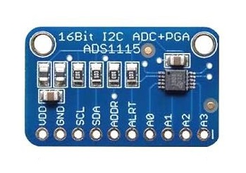
What is ADS1115 16-Bit ADC
Interfacing an ADS1115 16-bit analog-to-digital converter (ADC) with an Arduino is a straightforward process that allows you to measure the analog voltage of a sensor or other device using the Arduino’s digital input. The ADS1115 is a high-precision, low-power ADC that can measure a wide range of voltage levels. It can be configured to measure a single-ended or differential input, and it has a programmable gain amplifier that allows you to adjust the sensitivity of the ADC.
To interface the ADS1115 with an Arduino, you will need to use an I2C communication interface. The ADS1115 has an I2C address that can be set to one of four values, allowing you to use up to four ADS1115 devices on the same I2C bus.
Hardware Components
You will require the following hardware for Interfacing ADS1115 16-Bit ADC with Arduino.
| S.no | Component | Value | Qty |
|---|---|---|---|
| 1. | Arduino UNO | – | 1 |
| 2. | ADC Module | ADS1115 | 1 |
| 3. | Breadboard | – | 1 |
| 4. | Jumper Wires | – | 1 |
Interfacing ADS1115 16-Bit ADC with Arduino
Get all the required components that are listed above in the hardware section. Once you have them all, follow the given steps:
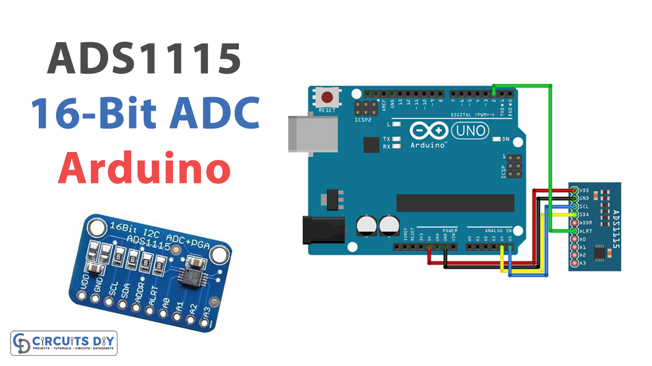
Schematic
Make connections according to the circuit diagram given below.
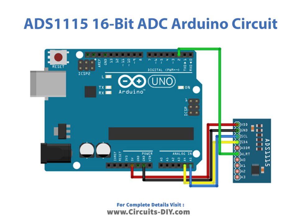
Wiring / Connections
| Arduino | ADS1115 Module |
|---|---|
| 5V | VCC |
| GND | GND |
| A4 | SDA |
| A5 | SCL |
| D2 | ALRT |
Installing Arduino IDE
First, you need to install Arduino IDE Software from its official website Arduino. Here is a simple step-by-step guide on “How to install Arduino IDE“.
Installing Libraries
Before you start uploading a code, download and unzip the following libraries at /Progam Files(x86)/Arduino/Libraries (default), in order to use the sensor with the Arduino board. Here is a simple step-by-step guide on “How to Add Libraries in Arduino IDE“.
Code
Now copy the following code and upload it to Arduino IDE Software.
// I2C device class (I2Cdev) demonstration Arduino sketch for ADS1115 class
// Example of reading two differential inputs of the ADS1115 and showing the value in mV
// 2016-03-22 by Eadf (https://github.com/eadf)
// Updates should (hopefully) always be available at https://github.com/jrowberg/i2cdevli
//
// Changelog:
//     2016-03-22 - initial release

/* ============================================
I2Cdev device library code is placed under the MIT license
Copyright (c) 2011 Jeff Rowberg

Permission is hereby granted, free of charge, to any person obtaining a copy
of this software and associated documentation files (the "Software"), to deal
in the Software without restriction, including without limitation the rights
to use, copy, modify, merge, publish, distribute, sublicense, and/or sell
copies of the Software, and to permit persons to whom the Software is
furnished to do so, subject to the following conditions:

The above copyright notice and this permission notice shall be included in
all copies or substantial portions of the software.

THE SOFTWARE IS PROVIDED "AS IS", WITHOUT WARRANTY OF ANY KIND, EXPRESS OR
IMPLIED, INCLUDING BUT NOT LIMITED TO THE WARRANTIES OF MERCHANTABILITY,
FITNESS FOR A PARTICULAR PURPOSE AND NONINFRINGEMENT. IN NO EVENT SHALL THE
AUTHORS OR COPYRIGHT HOLDERS BE LIABLE FOR ANY CLAIM, DAMAGES OR OTHER
LIABILITY, WHETHER IN AN ACTION OF CONTRACT, TORT OR OTHERWISE, ARISING FROM,
OUT OF OR IN CONNECTION WITH THE SOFTWARE OR THE USE OR OTHER DEALINGS IN
THE SOFTWARE.
===============================================
*/

#include "ADS1115.h"

ADS1115 adc0(ADS1115_DEFAULT_ADDRESS);

// Wire ADS1115 ALERT/RDY pin to Arduino pin 2
const int alertReadyPin = 2;

void setup() {
    //I2Cdev::begin();  // join I2C bus
    Wire.begin();
    Serial.begin(115200); // initialize serial communication

    Serial.println("Testing device connections...");
    Serial.println(adc0.testConnection() ? "ADS1115 connection successful" : "ADS1115 connection failed");

    adc0.initialize(); // initialize ADS1115 16 bit A/D chip

    // We're going to do single shot sampling
    adc0.setMode(ADS1115_MODE_SINGLESHOT);

    // Slow things down so that we can see that the "poll for conversion" code works
    adc0.setRate(ADS1115_RATE_250);

    // Set the gain (PGA) +/- 6.144v
    // Note that any analog input must be higher than –0.3V and less than VDD +0.3
    adc0.setGain(ADS1115_PGA_6P144);
    // ALERT/RDY pin will indicate when conversion is ready

    pinMode(alertReadyPin,INPUT_PULLUP);
    adc0.setConversionReadyPinMode();

    // To get output from this method, you'll need to turn on the
    //#define ADS1115_SERIAL_DEBUG // in the ADS1115.h file
    #ifdef ADS1115_SERIAL_DEBUG
    adc0.showConfigRegister();
    Serial.print("HighThreshold="); Serial.println(adc0.getHighThreshold(),BIN);
    Serial.print("LowThreshold="); Serial.println(adc0.getLowThreshold(),BIN);
    #endif
}

/** Poll the assigned pin for conversion status
 */
void pollAlertReadyPin() {
  for (uint32_t i = 0; i<100000; i++)
    if (!digitalRead(alertReadyPin)) return;
   Serial.println("Failed to wait for AlertReadyPin, it's stuck high!");
}

void loop() {

    // The below method sets the mux and gets a reading.
    adc0.setMultiplexer(ADS1115_MUX_P0_NG);
    adc0.triggerConversion();
    pollAlertReadyPin();
    Serial.print("A0: "); Serial.print(adc0.getMilliVolts(false)); Serial.print("mV\t");

    adc0.setMultiplexer(ADS1115_MUX_P1_NG);
    adc0.triggerConversion();
    pollAlertReadyPin();
    Serial.print("A1: "); Serial.print(adc0.getMilliVolts(true)); Serial.print("mV\t");

    adc0.setMultiplexer(ADS1115_MUX_P2_NG);
    adc0.triggerConversion();
    pollAlertReadyPin();
    Serial.print("A2: "); Serial.print(adc0.getMilliVolts(true)); Serial.print("mV\t");

    adc0.setMultiplexer(ADS1115_MUX_P3_NG);
    // Do conversion polling via I2C on this last reading:
    Serial.print("A3: "); Serial.print(adc0.getMilliVolts(true)); Serial.print("mV");

    Serial.println(digitalRead(alertReadyPin));
    delay(500);
*/
Let’s Test It
Once you are done with the circuit wiring and the uploading of code, it is now time to test the circuit. Open the serial monitor to observe the readings.
Working Explanation
Since the work relies on coding, it is essential to understand coding.
- This code reads voltage values from four analog input pins (A0-A3) on an ADS1115 analog-to-digital converter (ADC). The ADC is connected to an Arduino using the I2C protocol.
- In the void setup function, the ADC is initialized, and its mode is set to single-shot sampling, which means it will perform a single conversion when triggered. The ADC’s rate and gain are also set. The rate determines how often the ADC performs conversions, and the gain determines the range of voltages that the ADC can measure. In this case, the rate is set to 250 samples per second, and the gain is set to +/- 6.144V.
- The ADC is triggered in the void loop function to perform a conversion for each of the four analog inputs (A0-A3). The
pollAlertReadyPinfunction is called after each trigger to wait for the conversion to be completed before reading the result. The getMilliVolts function is then used to read the conversion result and convert it to millivolts. The resulting millivolt values are printed on the serial monitor.
Applications
- High-precision instrumentation
- Automotive electronics
- Battery voltage collection
Conclusion.
We hope you have found this Interfacing ADS1115 Arduino Circuit very useful. If you feel any difficulty in making it feel free to ask anything in the comment section.