Introduction
Are you ready to take your projects to the next level with wireless communication? The NRF24L01 wireless transceiver module is a powerful and easy-to-use tool that can help you achieve that. This tutorial will show you how to connect an Arduino board to an NRF24L01 module and use it to send and receive data wirelessly.
So let’s get started and explore the exciting world of wireless communication with the NRF24L01 module and Arduino!
What is Wireless Transceiver Module?
The functions of a transmitter and a receiver are combined into a single device known as a transceiver. Although the phrase is most often used to refer to equipment for wireless communication, it can also be used for transmitter/receiver devices found in cable or optical fiber networks.
This electronic device’s primary purpose is to send and receive various signals, making it an excellent communication tool.
Hardware Components
You will require the following hardware for Interfacing NRF24L01 Wireless Transceiver Module with Arduino.
| S.no | Component | Value | Qty |
|---|---|---|---|
| 1. | Arduino UNO | – | 1 |
| 2. | Power Module 3.3V | AMS1117 | 1 |
| 3. | RF Module | NRF24L01 | 1 |
| 4. | Breadboard | 2.4GHz | 1 |
| 5. | Jumper Wires | – | 1 |
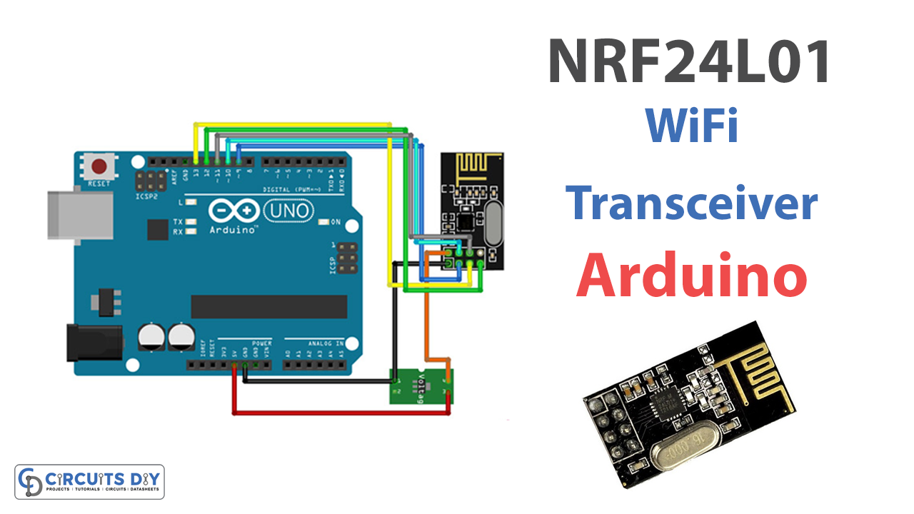
NRF24L01 Wireless Transceiver Module with Arduino
With the hardware and software in place, you can start sending and receiving data wirelessly with the NRF24L01 module and Arduino. But for this, you need to follow the given steps:
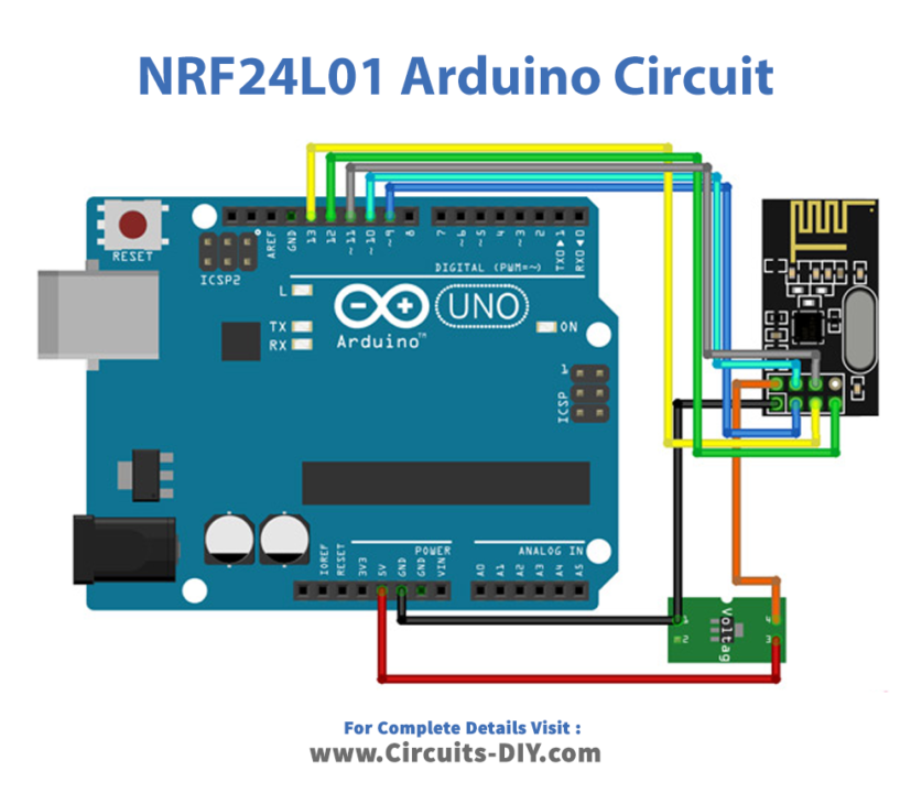
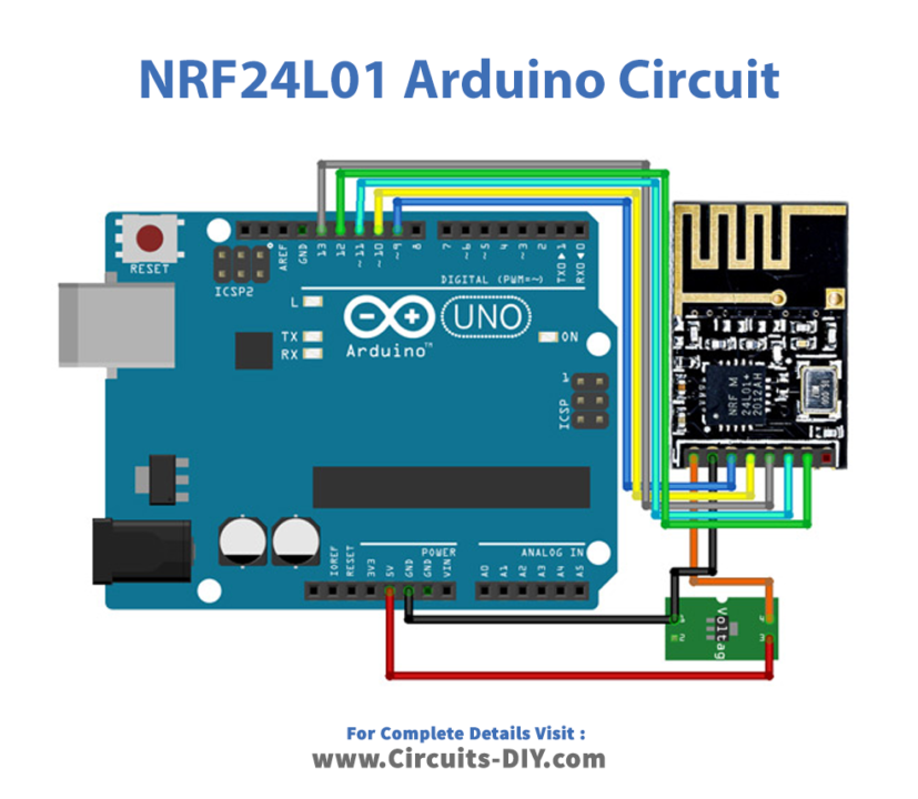
Schematic
Make connections according to the circuit diagram given below.
Installing Arduino IDE
First, you need to install Arduino IDE Software from its official website Arduino. Here is a simple step-by-step guide on “How to install Arduino IDE“.
Installing Libraries
Before you start uploading a code, download and unzip the following libraries at /Progam Files(x86)/Arduino/Libraries (default), in order to use the sensor with the Arduino board. Here is a simple step-by-step guide on “How to Add Libraries in Arduino IDE“.
Code
Now copy the following code and upload it to Arduino IDE Software.
Receiver
/* 1 ch NRF 24 TRANSMITTER example.

  Module // Arduino UNO //        ESP32
    GND    ->   GND           ->  GND
    Vcc    ->   3.3V(External)->  3.3v
    CE     ->   D9            ->  D4
    CSN    ->   D10           ->  D5
    CLK    ->   D13           ->  D18
    MOSI   ->   D11           ->  D23
    MISO   ->   D12           ->  D19
*/

/* First we include the libraries. Download it from
   my webpage if you donw have the NRF24 library */
#include <SPI.h>
#include <nRF24L01.h>
#include <RF24.h>
#include <printf.h>

/*//////////////////////////////////////////////////////*/

#if defined(__AVR_ATmega328P__) || defined(__AVR_ATmega328PB__) ||defined(__AVR_ATmega2560__) || defined(__AVR_ATmega1280__)
#define CSN 10
#define CE  9
#elif defined(ESP32)
#define CSN 5
#define CE  4
#else
#error "Make Config you're self"
#endif

#define Debug_mode false

/*Create a unique pipe out. The receiver has to
  wear the same unique code*/
const uint64_t pipeIn = 0x662266; //IMPORTANT: The same as in the receiver!!!
/*//////////////////////////////////////////////////////*/

/*Create the data struct we will send
  The sizeof this struct should not exceed 32 bytes
  This gives us up to 32 8 bits channals */
RF24 radio(CE, CSN); // select  CSN and CE  pins


/*//////////////////////////////////////////////////////*/
//Create a struct to send over NRF24
struct MyData {
  byte test;
};
MyData data;
/*//////////////////////////////////////////////////////*/

//This function will only set the value to  0 if the connection is lost...
void resetData()
{
  data.test = 0;
}


/**************************************************/

void setup()
{
  pinMode(LED_BUILTIN, OUTPUT);
  Serial.begin(9600); //Set the speed to 9600 bauds if you want.
  //You should always have the same speed selected in the serial monitor
  resetData();
  radio.begin();
  if (Debug_mode)
    printf_begin();
  radio.setDataRate(RF24_250KBPS); //speed  RF24_250KBPS for 250kbs, RF24_1MBPS for 1Mbps, or RF24_2MBPS for 2Mbps
  radio.openWritingPipe(pipeIn);//Open a pipe for writing
  radio.openReadingPipe(1, pipeIn);//Open a pipe for reading
  radio.openReadingPipe(2, pipeIn);//Open a pipe for reading
  radio.openReadingPipe(3, pipeIn);//Open a pipe for reading
  radio.openReadingPipe(4, pipeIn);//Open a pipe for reading
  radio.openReadingPipe(5, pipeIn);//Open a pipe for reading
  radio.setAutoAck(true); // Ensure autoACK is enabled
  radio.setChannel(108);// Set RF communication channel.
  radio.setPALevel(RF24_PA_MAX); //translate to: RF24_PA_MIN=-18dBm, RF24_PA_LOW=-12dBm, RF24_PA_MED=-6dBM, and RF24_PA_HIGH=0dBm.
  radio.enableDynamicPayloads(); //This way you don't always have to send large packets just to send them once in a while. This enables dynamic payloads on ALL pipes.
  //radio.disableDynamicPayloads();//This disables dynamic payloads on ALL pipes. Since Ack Payloads requires Dynamic Payloads, Ack Payloads are also disabled. If dynamic payloads are later re-enabled and ack payloads are desired then enableAckPayload() must be called again as well.
  radio.setCRCLength(RF24_CRC_16); // Use 8-bit or 16bit CRC for performance. CRC cannot be disabled if auto-ack is enabled. Mode :RF24_CRC_DISABLED  ,RF24_CRC_8 ,RF24_CRC_16
  radio.setRetries(10, 15);//Set the number of retry attempts and delay between retry attempts when transmitting a payload. The radio is waiting for an acknowledgement (ACK) packet during the delay between retry attempts.Mode: 0-15,0-15
  radio.startListening();//Start listening on the pipes opened for reading.
}


/******Reset the received data to 0 if connection is lost******/
unsigned long lastRecvTime = 0;
void recvData()
{
  while ( radio.available() )//Check whether there are bytes available to be read
  {
    radio.read(&data, sizeof(MyData));//Read payload data from the RX FIFO buffer(s).
    lastRecvTime = millis(); //here we receive the data
  }
}
/**************************************************************/


void loop()
{
  recvData(); //Resive Data
  unsigned long now = millis();
  //Here we check if we've lost signal, if we did we reset the values
  if ( now - lastRecvTime > 1000 ) {
    // Signal lost?
    resetData();
  }
  Serial.print("Resive Value: "); Serial.println(data.test);
  analogWrite(LED_BUILTIN, data.test);
  delay(100);
  if (Debug_mode)
    radio.printDetails();//Show debug data
}
Transmitter
/* 1 ch NRF 24 TRANSMITTER example.

  Module // Arduino UNO //        ESP32
    GND    ->   GND           ->  GND
    Vcc    ->   3.3V(External)->  3.3v
    CE     ->   D9            ->  D4
    CSN    ->   D10           ->  D5
    CLK    ->   D13           ->  D18
    MOSI   ->   D11           ->  D23
    MISO   ->   D12           ->  D19
*/

First, we include the libraries. Download it from
   my webpage if you done have the NRF24 library */
#include <SPI.h>
#include <nRF24L01.h>
#include <RF24.h>
#include <printf.h>

/*//////////////////////////////////////////////////////*/

#if defined(__AVR_ATmega328P__) || defined(__AVR_ATmega328PB__) ||defined(__AVR_ATmega2560__) || defined(__AVR_ATmega1280__)
#define CSN 10
#define CE  9
#elif defined(ESP32)
#define CSN 5
#define CE  4
#else
#error "Make Config you're self"
#endif

#define Debug_mode false


Create a unique pipeout. The receiver has to
  wear the same unique code*/
const uint64_t pipeOut = 0x662266; //IMPORTANT: The same as in the receiver!!!
/*//////////////////////////////////////////////////////*/

/*Create the data struct we will send
  The sizeof this struct should not exceed 32 bytes
  This gives us up to 32 8 bits channals */

RF24 radio(CE, CSN); // select  CSN and CE  pins


/*//////////////////////////////////////////////////////*/
//Create a struct to send over NRF24
struct MyData {
  byte test;
};
MyData data;
byte count = 0;
/*//////////////////////////////////////////////////////*/


//This function will only set the value to  0 if the connection is lost...
void resetData()
{
  data.test = 0;
}

void setup()
{
  Serial.begin(9600);
  if (Debug_mode)
    printf_begin();
  radio.begin();
  radio.setDataRate(RF24_250KBPS); //speed  RF24_250KBPS for 250kbs, RF24_1MBPS for 1Mbps, or RF24_2MBPS for 2Mbps
  radio.openWritingPipe(pipeOut); //Open a pipe for writing
  radio.openReadingPipe(0, pipeOut); //Open a pipe for reading
  radio.setChannel(108);// Set RF communication channel.
radio.setPALevel(RF24_PA_MAX); //translates to: RF24_PA_MIN=-18 dBm, RF24_PA_LOW=-12 dBm, RF24_PA_MED=-6 dBm, and RF24_PA_HIGH=0 dBm.
  radio.enableDynamicPayloads(); // // This way, you don't always have to send large packets just to send them once in a while. This enables dynamic payloads on all pipes.
  //radio.disableDynamicPayloads();//This disables dynamic payloads on all pipes. Since Ack payloads require dynamic payloads, Ack payloads are also disabled. If dynamic payloads are later re-enabled and ack payloads are desired, then enableAckPayload() must be called again as well.
  radio.setCRCLength(RF24_CRC_16); // Use an 8-bit or 16-bit CRC for performance. CRC cannot be disabled if auto-ack is enabled. Mode :RF24_CRC_DISABLED  ,RF24_CRC_8 ,RF24_CRC_16
  radio.setRetries(10, 15);//Set the number of retry attempts and delay between retry attempts when transmitting a payload. The radio is waiting for an acknowledgement (ACK) packet during the delay between retry attempts. Mode: 0-15,0-15
  radio.setAutoAck(true); // Ensure autoACK is enabled
  radio.stopListening();//Stop listening for incoming messages, and switch to transmit mode.
  resetData();

}

/**************************************************/

void loop()
{
  count++;
  data.test = count;//fill data to MyData
  Serial.print("Send");
  Serial.println(count);
  if (count == 254) {
    count = 0;
  }
  NRF24_Transmit();//Transmit MyData
  delay(200);
}

void NRF24_Transmit() {
  radio.writeFast(&data, sizeof(MyData));//Transmit Data. Use one of these two: write() or writeFast()
  if (Debug_mode)
    radio.printDetails();//Show debug data
  bool OK = radio.txStandBy();//Returns 0 if failed. 1 if there is success.
  delayMicroseconds(50);
  radio.flush_tx();//Empty all 3 of the TX (transmit) FIFO buffers
}
Let’s Test It
Once you build the connections, upload the above codes to your Arduino. The purpose of these codes is to test if the two Arduino boards are properly connected to one another.
Once the Arduinos get power, data will be shown on the serial monitor.
Working Explanation
The circuit does nothing without the code. And that’s why it’s essential to understand the program in order to understand the working.
Receiver Side
- The #include statements at the top of the sketch, including libraries for using the NRF24L01+ radio module and the Serial interface on the microcontroller. The #include <SPI.h> and #include <nRF24L01.h> libraries are required for using the NRF24L01+ module, and the #include <RF24.h> library provides a higher-level interface for using the module. The #include <printf.h> library is optional and provides the printf() function for printing.
- The sketch defines some constants for the chip select (CSN) and chip enable (CE) pins used to control the NRF24L01+ module.
- The sketch also defines a constant called pipeIn, representing a unique 64-bit address used to identify the radio module on the receiving end. The receiving module must be programmed with the same address to receive the data.
- The sketch then defines a struct called MyData which will be used to hold the data that is being sent. In this case, the struct only has a single member called test.
- The sketch then creates an instance of the RF24 class called radio and initializes it with the values of the CSN and CE pins.
- In the setup() function, the sketch initializes the radio module and sets up a pipe for sending and receiving data. It also sets the radio module’s data rate, channel, and output power level. It also enables automatic acknowledgment (ACK) of received packets and sets the length of the cyclic redundancy check (CRC) used for error detection. The sketch then starts listening for incoming packets on the open pipes.
- The recvData() function receives data from the radio module. It reads any available data from the radio module and stores it in the MyData struct. It also updates a variable called lastRecvTime with the current time to track when the last packet was received.
- The sendData() function sends data over the radio module. It sends the contents of the MyData struct over the radio using the write() function of the RF24 class.
- The loop() function is the main loop of the program. It calls the recvData() and sendData() functions to receive and send data. It also checks if the connection with the receiving module has been lost by checking the value of lastRecvTime and calling the resetData() function if connection has been lost.
Transmitter Side
- The #include statements at the top of the sketch, including libraries
- The sketch defines some constants for the chip select (CSN) and chip enable (CE) pins used to control the NRF24L01+ module.
- The sketch also defines a constant called pipeOut, which represents a unique 64-bit address used to identify the radio module on the receiving end. The receiving module must be programmed with the same address to receive the data.
- The sketch then defines a struct called MyData which will be used to hold the data that is being sent. In this case, the struct only has a single member called test.
- The sketch then creates an instance of the RF24 class called radio and initializes it with the values of the CSN and CE pins.
- In the setup() function, the sketch initializes the radio module and sets up a pipe for sending data. It also sets the radio module’s data rate, channel, and output power level. It also enables automatic acknowledgment (ACK) of received packets and sets the length of the cyclic redundancy check (CRC) used for error detection. The sketch then stops listening for incoming packets and switches to transmit mode.
- The loop() function is the main loop of the program. It increments a counter called count and stores it in the test field of the MyData struct. It then calls the NRF24_Transmit() function to send the MyData struct over the radio. The loop then waits for 200 milliseconds before repeating.
- The NRF24_Transmit() function sends the MyData struct over the radio. It uses the writeFast() function of the RF24 class to send the data. If the Debug_mode constant is true, the function also prints some debug information to the serial console using the printDetails() function. The function then waits for 50 microseconds before returning.
Applications
- Wireless control applications.
- RF Remote Controllers
Conclusion.
We hope you have found this Interfacing NRF24L01 Wireless Transceiver Module with Arduino Circuit very useful. If you feel any difficulty in making it feel free to ask anything in the comment section.