Introduction
In this tutorial, we are going to “Interface MT8870 DTMF Decoder Module with Arduino”. The DTMF Decoder Module based on the MT8870 is often used to operate robots using a mobile phone; it is also utilized in other types of home automation applications that need mobile dial pad input. This module functions as a tone decoder, receiving input audio signals through its 3.5 mm audio connection socket. It is often used for voice dialing and recording functionalities on mobile and landline telephones.
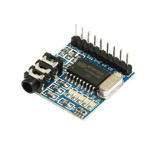
Overview of MT880
A 4-bit digital code is produced by the DTMF Decoder Module MT8870 with regard to the DTMF audio stream. The operational amplifier of the MT8870 Decoder IC has a user-adjustable Guard time. Switch capacitor techniques are used by the embedded band-split filter to separate and separate low and high frequencies from the received signal. The module has an audio connection to accept the produced DTMF signal.
Working of Module
The IC features a digital code detector and converter, as well as an operational amplifier and filter network. The audio signal input is sent to the operational amplifier. To separate the audio signal into distinct frequency groups, the amplified signal is sent to the filter network, which consists of a pre-processing dial tone filter, low-frequency filter, and high-frequency filter. A 4-bit output binary code is generated in response to the detecting circuitry detecting the filtered frequencies. The states of the output LEDs are then used to visually demonstrate the code, and if the output pins are connected to a microcontroller unit, they may also be shown on a PC.
Features
- Onboard 3.5mm jack input Facility
- MT8870 Based Frequency Decoder
- 5 Channel Interface
- Detects 0-9, A-D, *, #
- LED notifier for Output state
- Low power consumption
- Internal gain setting amplifier
- Onboard LED, it is very convenient to check the output state.
- Adjustable guard time
- Central office quality
- Power-down mode
- Inhibit mode
- Onboard audio input interface
- Onboard LED lights for output state indication Complete DTMF Receiver.
- Does not require external circuits or wiring, it can be inserted directly into the UNO/MEGA2560/DUE board to use.
Hardware Required
| S.no | Component | Value | Qty |
|---|---|---|---|
| 1. | Arduino UNO | – | 1 |
| 2. | USB Cable Type A to B | – | 1 |
| 3. | Audio Decoder Module | MT8870 DTMF | 1 |
| 4. | Jumper Wires | – | – |
| 5. | Cell Phone | – | 1 |
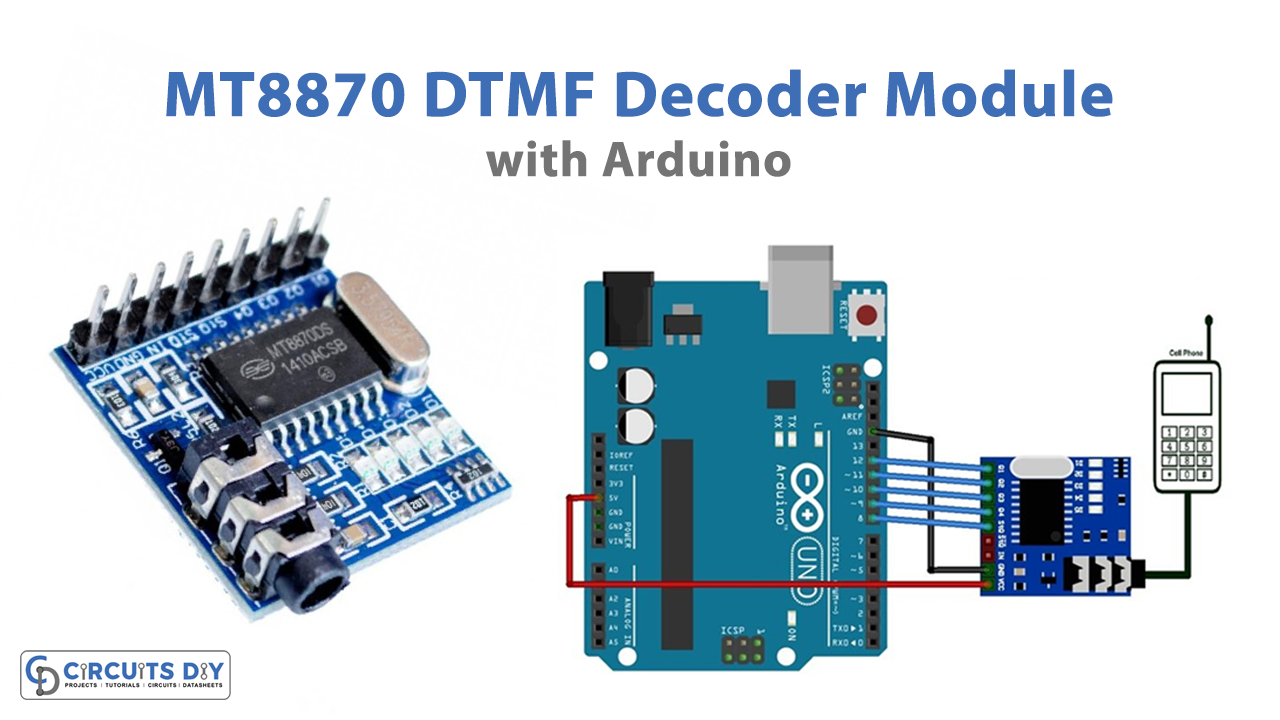
Circuit Diagram
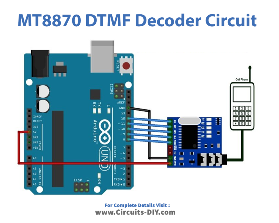
Connection Table
| Arduino UNO | MT8870 DTMF |
|---|---|
| GND | GND |
| 5v | Vcc |
| D8 | StD |
| D9 | Q4 |
| D10 | Q3 |
| D11 | Q2 |
| D12 | Q1 |
Arduino Code
/*Define input pins for DTMF Decoder pins connection */
void setup() {
  Serial.begin(9600);
  pinMode(8, INPUT); // connect to Std pin
  pinMode(9, INPUT); // connect to Q4 pin
  pinMode(10, INPUT); // connect to Q3 pin
  pinMode(11, INPUT); // connect to Q2 pin
  pinMode(12, INPUT); // connect to Q1 pin
}

void loop() {
  uint8_t number_pressed;
  bool signal ;
  signal = digitalRead(3);
  if(signal == HIGH)  /* If new pin pressed */
   {
    delay(250);
    number_pressed = ( 0x00 | (digitalRead(7)<<0) | (digitalRead(6)<<1) | (digitalRead(5)<<2) | (digitalRead(4)<<3) );
      switch (number_pressed)
      {
        case 0x01:
        Serial.println("Button Pressed =  1");
        break;
        case 0x02:
        Serial.println("Button Pressed =  2");
        break;
        case 0x03:
        Serial.println("Button Pressed =  3");
        break;
        case 0x04:
        Serial.println("Button Pressed =  4");
        break;
        case 0x05:
        Serial.println("Button Pressed =  5");
        break;
        case 0x06:
        Serial.println("Button Pressed =  6");
        break;
        case 7:
        Serial.println("Button Pressed =  7");
        break;
        case 0x08:
        Serial.println("Button Pressed =  8");
        break;
        case 0x09:
        Serial.println("Button Pressed =  9");
        break;
        case 0x0A:
        Serial.println("Button Pressed =  0");
        break;
        case 0x0B:
        Serial.println("Button Pressed =  *");
        break;
        case 0x0C:
        Serial.println("Button Pressed =  #");
        break;
      }
  }
}
Working Explanation
To Interface MT8870 DTMF Decoder Module with Arduino connect the circuit according to the given diagram, and upload the code. Select a key from the dial pad. For example, 2 is entered into the dial pad. The number 2 will generate a unique DTMF signal. The module receives, distinguishes, and creates a 4-bit binary code, which is then sent to the Arduino. The value is processed by the MCU, which outputs “Pin Pressed: 2.” Try various numbers and see what happens.
Code Explanation
- The Serial monitor is initialized in the void setup function to display the key in relation to the binary code. This loop also defines the pin modes for determining the value of the pin using the digitalRead method.
- The void loop initializes the variables “number” and “signal” to hold the binary code received from the DTMF module. When a key on the keypad is hit, it goes high, and the loop executes the if loop. The digitalRead function takes the value from pins 12, 11, 10, and 9; Q1, Q2, Q3, and Q4, respectively, and stores it in the number variable. The stored value is then compared to all of the situations. The case where the value matches would be run and the outcome will be displayed on the Serial monitor.
Application and Uses
- Smartphones
- Robotics
- Industrial automation
- Telecommunication devices, etc