Introduction
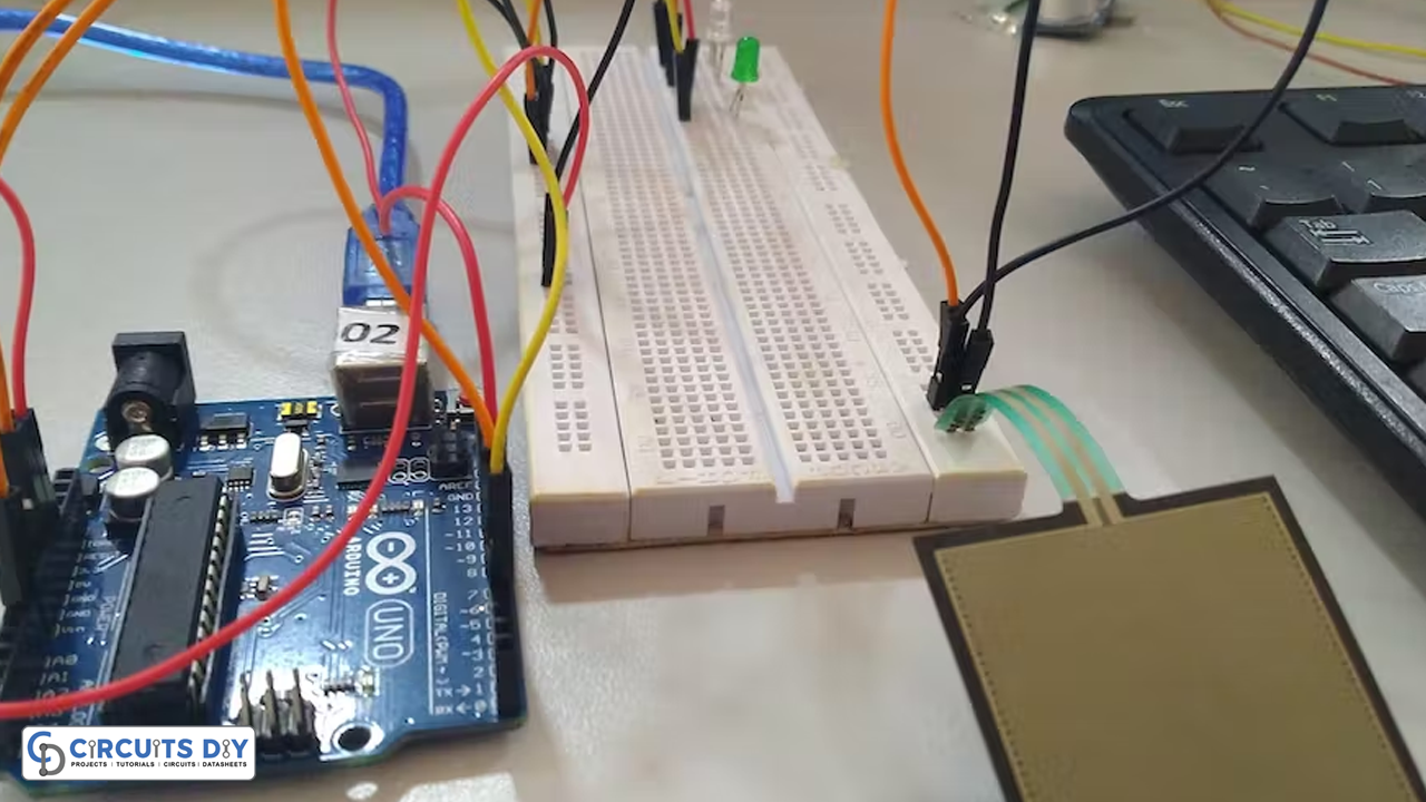
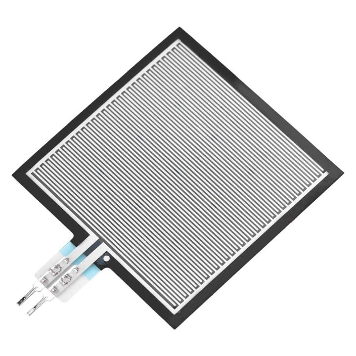
This article is about Pressure Pad Interfacing with Arduino. Pressure pads come in a variety of quality and accuracy levels and are made to detect when pressure is applied to an area. Simple pressure pads are frequently comparable to large switches.
A pressure pad can be used for a wide range of purposes, including monitoring when someone takes a seat or applies pressure to a particular area of an object. It’s an exceptionally good sensor to use for IoT projects and other things.
What is a Pressure Pad?
A pressure pad sensor is an electronic device that measures the pressures applied to any two objects. The Pressure Pad Sensor is typically made up of several sensing components arranged in an array on or within a flexible cushion. This device maps the forces between contacting surfaces in real time.
Hardware Components
You will require the following hardware for Pressure Pad Interfacing with Arduino.
| S.no | Component | Value | Qty |
|---|---|---|---|
| 1. | Arduino UNO | – | 1 |
| 2. | Pressure Pad | SEN-09376 | 1 |
| 3. | LED | – | 1 |
| 4. | Resistor | 3.3KΩ | 1 |
| 5. | Breadboard | – | 1 |
| 6. | Jumper Wires | – | 1 |
Steps Interfacing Pressure Pad
For the interfacing of the pressure pad and Arduino, very fewer components are required. Once you have them all; follow the steps given below:
Schematic
Make connections according to the circuit diagram given below.
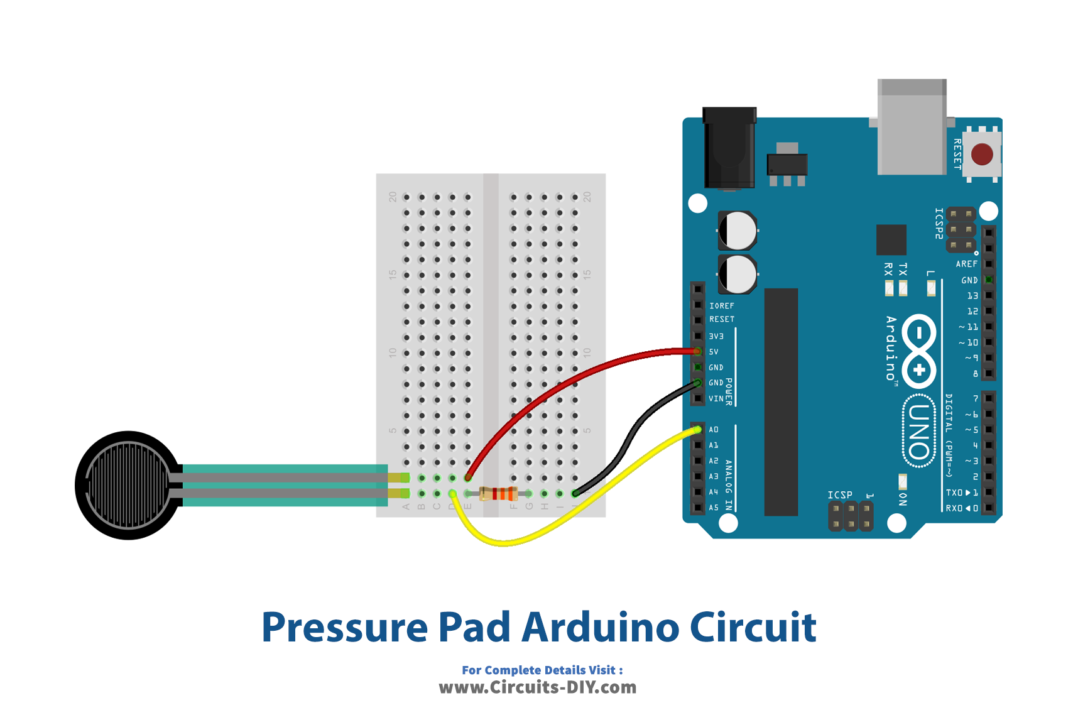
Wiring / Connections
| Arduino | Pressure Pad | Resistor |
|---|---|---|
| 5V | 1st Pin | |
| GND | 2nd Pin | 1st Pin |
| A0 | 2nd Pin |
Installing Arduino IDE
First, you need to install Arduino IDE Software from its official website Arduino. Here is a simple step-by-step guide on “How to install Arduino IDE“.
Code
Now copy the following code and upload it to Arduino IDE Software.
const int FSR_PIN = A0; // Pin connected to FSR/resistor divider
const int LED_PIN1 = 7;
const int LED_PIN2 = 6;
const int LED_PIN3 = 4;
const float VCC = 4.98; // Measured voltage of Ardunio 5V line
const float R_DIV = 3230.0; // Measured resistance of 3.3k resistor

void setup()
{
  Serial.begin(9600);
  pinMode(FSR_PIN, INPUT);
  pinMode(LED_PIN1, OUTPUT);
  pinMode(LED_PIN2, OUTPUT);
  pinMode(LED_PIN3, OUTPUT);
}

void loop()
{
  int fsrADC = analogRead(FSR_PIN);
  // If the FSR has no pressure, the resistance will be
  // near infinite. So the voltage should be near 0.
  if (fsrADC != 0) // If the analog reading is non-zero
  {
    // Use ADC reading to calculate voltage:
    float fsrV = fsrADC * VCC / 1023.0;
    // Use voltage and static resistor value to
    // calculate FSR resistance:
    float fsrR = R_DIV * (VCC / fsrV - 1.0);
    Serial.println("Resistance: " + String(fsrR) + " ohms");
    // Guesstimate force based on slopes in figure 3 of
    // FSR datasheet:
    float force;
    float fsrG = 1.0 / fsrR; // Calculate conductance
    // Break parabolic curve down into two linear slopes:
    if (fsrR <= 600)
      force = (fsrG - 0.00075) / 0.00000032639;
    else
      force =  fsrG / 0.000000642857;
    Serial.println("Force: " + String(force) + " g");
    Serial.println();
    if(force<10)
    {
       digitalWrite(LED_PIN1,LOW);
      digitalWrite(LED_PIN2,LOW);
      digitalWrite(LED_PIN3,LOW);}
    if(force>20)
    {
      digitalWrite(LED_PIN1,HIGH);
      digitalWrite(LED_PIN2,LOW);
      digitalWrite(LED_PIN3,LOW);

    }
    if(force>60)
    {
      digitalWrite(LED_PIN2,HIGH);
      digitalWrite(LED_PIN1,LOW);
      digitalWrite(LED_PIN3,LOW);
    }
    if(force>100)
    {
       digitalWrite(LED_PIN3,HIGH);
      digitalWrite(LED_PIN2,LOW);
      digitalWrite(LED_PIN1,LOW);
    }

    delay(500);

  }
  else
  {
    // No pressure detected
  }
}
Let’s Test It
It’s now time to test the circuit. As soon as you apply pressure after powering up the Arduino, you will see the LEDs glowing according to the pressure applied. You’ll also observe the readings coming to your serial monitor.
Working Explanation
Let’s dig into the coding for a proper understanding of this circuit:
- First, we define and name the pins of an Arduino that are being used in the circuit. Also, we define two float variables of measured voltage and resistance which will be used further in the code.
- In the void setup, we first initialize the serial monitor. Then we declared the status of the defined pins of Arduino as input or output.
- In the void loop, we first read the values coming from the sensor. We then also give the condition that if the coming value is not equal to zero; only in that case does the code proceed further. It then calculates voltage using the ADC reading, calculates FSR resistance using voltage and the static resistor value, then prints resistance and calculates conductance. After that, the code will measure force and print that. Now there are conditions and combinations of LED pins to glow. For example; if the force is less than 10 all three LEDs will not glow, if its greater than 20 LED 1 glows; etc
Applications
- Security Systems
- Intruder alarm; et
Conclusion
We hope you have found this Pressure Pad Interfacing with Arduino Circuit very useful. If you feel any difficulty in making it feel free to ask anything in the comment section.

