Introduction
In engineering, whether it is a DC motor, a servo motor, or a stepper motor, industries cannot function without them. These motors are employed in consumer and robotics applications and industrial machines. So we’ve opted to talk about a stepper motor, one of those motors. The name “stepper motor” comes from each electrical pulse that causes the motor to take one step. A pulsed electrical current is transformed into a precise one-step in the stepper motor, controlled by a stepper motor driver. Stepper motors are controlled by a driver, which sends pulses into the motor, causing it to rotate. There are many driver modules to control these motors. One of them is DRV8825. Hence, In this tutorial, we will interface the ” DRV8825 Driver Module with Arduino UNO”.
DRV8825 Motor Driver Module
The DRV8825 is a complete Microstepping Motor Driver with an easy-to-use built-in translator. Texas Instruments breakout board has configurable current limiting, over-current and over-temperature safety, and six micro-step resolutions. It runs between 8.2 and 45 volts and can produce up to 1.5 amps per phase without using a heat sink or forced airflow. It has a current rating of 2.2 A per coil and adequate cooling.
Features and Specification
- Max. Operating Voltage: 45 V
- Min. Operating Voltage: 8.2 V
- Max. Current Per Phase: 2.5 A
- PCB Size: 15 mm x 20 mm
- Six step resolution: Full step, ½ step, ¼ step, 1/8, 1/16 and 1/32 step
- Adjustable output current via potentiometer
- Automatic current decay mode detection
- Over-temperature shutdown circuit
- Under-voltage lockout
- Over-current shutdown
Pinouts
| Pin Name | Description |
| VDD & GND | Connected to 5V and GND of Controller |
| VMOT & GND MOT | Used to power the motor |
| B1, B2 & A1, A2 | Output Pins, Connected to the 4 Wires of motor |
| DIRECTION | Motor Direction Control pin |
| STEP | Steps Control Pin |
| M0, M1, M2 | Microstep Selection Pins |
| FAULT | Fault Detection Pin |
| SLEEP | Pins For Controlling Power States |
| RESET | |
| ENABLE |

Hardware Required
| S.no | Components | Value | Qty |
|---|---|---|---|
| 1 | Arduino UNO | – | 1 |
| 2 | USB Cable Type A to B | – | 1 |
| 3 | Jumper Wires | – | – |
| 4 | Stepper Motor Driver Module | DRV8825 | 1 |
| 5 | Adapter | 12V | 1 |
| 6 | Capacitor | 10uf | 1 |
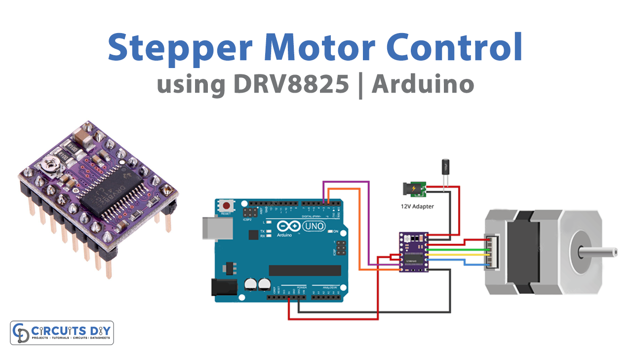
Circuit Diagram

Connection Table
| Arduino | DRV8825 Driver Module |
|---|---|
| VCC | SLP, RST |
| GND | GND |
| D2 | Step |
| D3 | DIR |
Arduino Code
// Define pin connections & motor's steps per revolution
const int dirPin = 2;
const int stepPin = 3;
const int stepsPerRevolution = 200;

void setup()
{
	// Declare pins as Outputs
	pinMode(stepPin, OUTPUT);
	pinMode(dirPin, OUTPUT);
}
void loop()
{
	// Set motor direction clockwise
	digitalWrite(dirPin, HIGH);

	// Spin motor slowly
	for(int x = 0; x < stepsPerRevolution; x++)
	{
		digitalWrite(stepPin, HIGH);
		delayMicroseconds(2000);
		digitalWrite(stepPin, LOW);
		delayMicroseconds(2000);
	}
	delay(1000); // Wait a second

	// Set motor direction counterclockwise
	digitalWrite(dirPin, LOW);

	// Spin motor quickly
	for(int x = 0; x < stepsPerRevolution; x++)
	{
		digitalWrite(stepPin, HIGH);
		delayMicroseconds(1000);
		digitalWrite(stepPin, LOW);
		delayMicroseconds(1000);
	}
	delay(1000); // Wait a second
}
Working Explanation
To Control Stepper Motor with DRV8825 Driver Module & Arduino, connect the circuit according to the circuit diagram or follow the connection table. Then write the above-given code in Arduino IDE, and upload that in the Arduino UNO. Now, you will observe the rotation of motors according to your code. It first moves in the clockwise direction to complete the prescribed steps at the defined speed then will move in the anti-clockwise direction at the same rate. Hence this is how the circuit works.
Code Explanation
- At first, we defined the driver pin that is connected to Arduino. We then defined the content stepsPerRevolution which holds the integer number of steps that the motor would take to complete per revolution.
- In the void setup, we have declared that defined pin as output.
- In the void loop, We rotate the motor gradually clockwise and then counterclockwise at a second interval. We set the DIR pin HIGH or LOW to regulate the motor’s spinning direction. The motor rotates clockwise when the input is HIGH, and anticlockwise when the input is LOW. The frequency of the pulses we transmit to the STEP pin determines the speed of a motor. The motor operates quicker when the pulses are higher. Pulses are just pulling the output HIGH, waiting a few seconds, then bringing it LOW and waiting some more. You may modify the frequency of two pulses and hence the speed of a motor by adjusting the delay between them.
Application and Uses
- In robotics, to convert electrical pulse into angular movements, or steps.
- Pulling filament into the extruder in a 3D printer.
- In CNC machines, to transform nonlinear input into linear movement.