Introduction
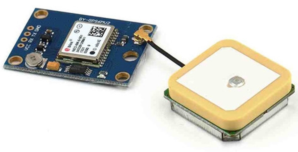
If you desire to give your device a high-performance, inexpensive GPS function then interface it with NEO-6M GPS Module. The module has the GPS chip of u-blox. This compact module can track almost 22 satellites on almost 50 channels. Moreover, it can provide updates of 5 locations. This feature is not available in many other GPS modules. Therefore, it makes the module more unique. Further, the module consumes 45mA of current and has the feature of power save module Hence this can reduce the current consumption to 11ma. Coming towards the board, the module has an LED that shows the status. It also contains the regulator of 3.3V and has two wire EEPROM there.
Moreover, there is a rechargeable button for the battery. Also, the module comes with an antenna which is needed for communication. So, this tutorial is all about interfacing ” 6M GPS Module with Arduino UNO”.
Hardware Required
| S.no | Component | Value | Qty |
|---|---|---|---|
| 1. | Arduino | UNO | 1 |
| 2. | USB Cable Type A to B | – | 1 |
| 3. | Jumper Wires | – | 1 |
| 4. | GPS Module | 6M | 1 |
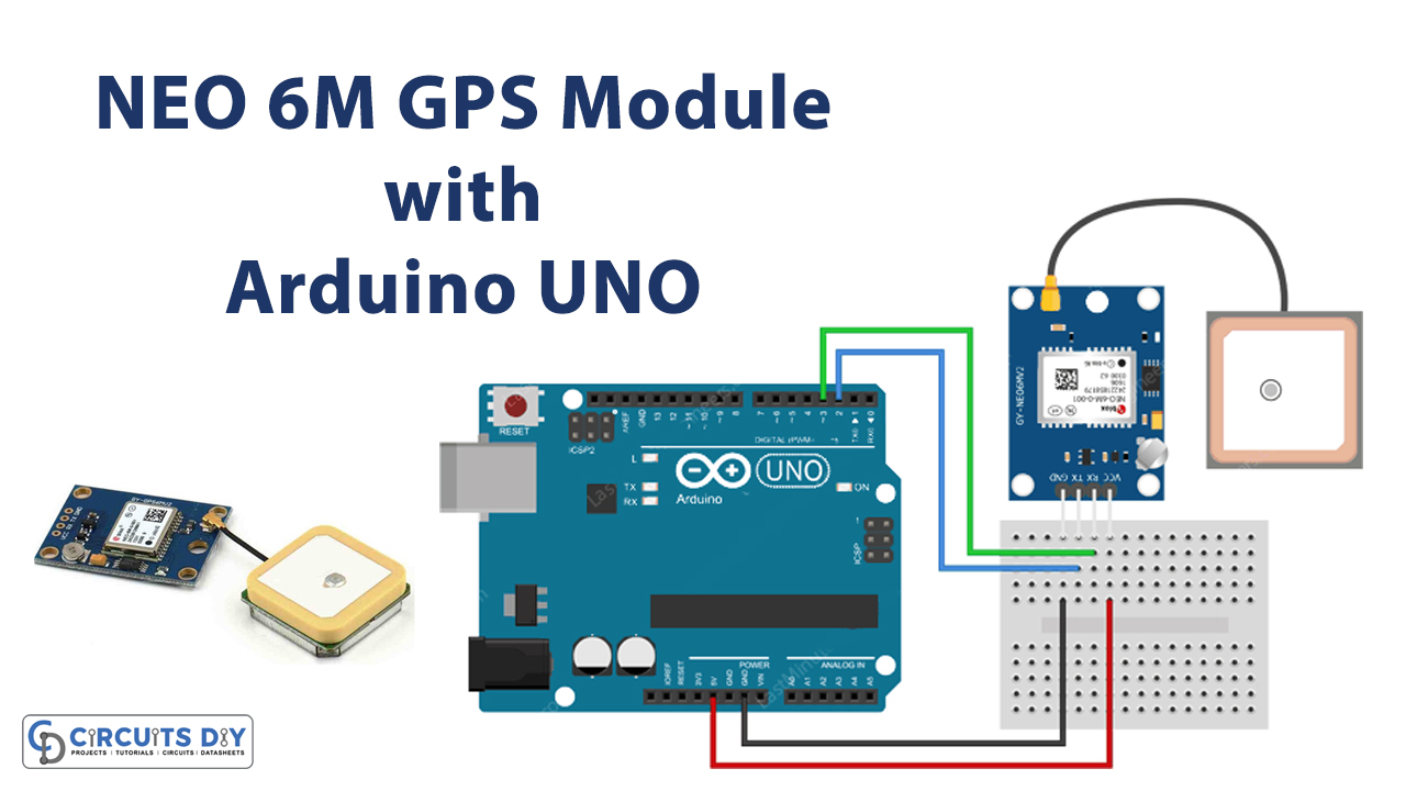
Circuit Diagram

Connection Table
| Arduino | 6M GPS Module |
|---|---|
| D2 | TX |
| D3 | RX |
| GND | GND |
| 5V | VCC |
Arduino Code
Reading GPS Data
#include <SoftwareSerial.h>

// Choose two Arduino pins to use for software serial
int RXPin = 2;
int TXPin = 3;

//Default baud of NEO-6M is 9600
int GPSBaud = 9600;

// Create a software serial port called "gpsSerial"
SoftwareSerial gpsSerial(RXPin, TXPin);

void setup()
{
  // Start the Arduino hardware serial port at 9600 baud
  Serial.begin(9600);

  // Start the software serial port at the GPS's default baud
  gpsSerial.begin(GPSBaud);
}

void loop()
{
  // Displays information when new sentence is available.
  while (gpsSerial.available() > 0)
    Serial.write(gpsSerial.read());
}
Working Explanation
Connect the NEO-6M GPS Module with Arduino UNO according to the diagram available in this tutorial. Copy the above-given code and paste it into your Arduino IDE. Now, upload that code and open the Serial monitor of IDE. Observe the readings when available.
Code Explanation
- Include the SoftwareSerial library in your code. Then define the Arduino pins that are connected to the receiver and transmitter pins of the module. Define the baud rate of the module. The default baud for this module is 9600. After that, create the object of the Software serial port called gpsSerial( ).
- In the void setup, initialize the serial monitor ny Serial.begin( ). Initialize the GPS by gpsSerial. begin( ).
- In the void loop, formulate the while loop to display information on the Serial monitor when available.
Related posts:
 Motion Sensor with Piezo Buzzer - Arduino Tutorial
 Interfacing TTP229 16 Key Capacitive Touch Keypad with Arduino
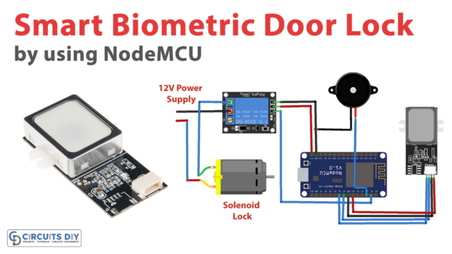 Smart Biometric Door Lock using NodeMCU and Fingerprint Sensor
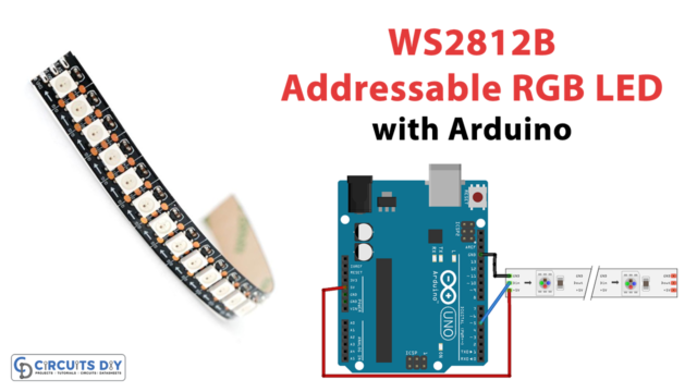 WS2812B Addressable RGB LED Interfacing with Arduino
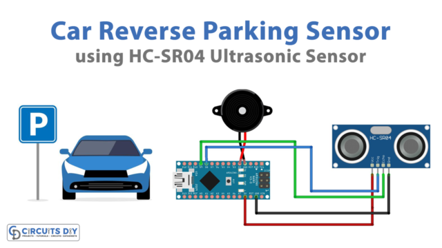 Car Reverse Parking Sensor Circuit
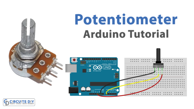 How to use a Potentiometer - Arduino Tutorial


