Introduction
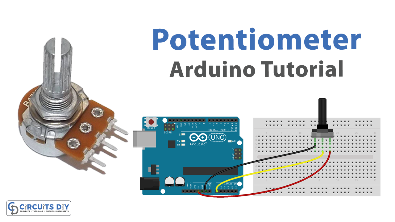
Reading an analog voltage level using a potentiometer and posting its status on the serial monitor using an Arduino Uno microcontroller is a process of measuring the voltage level at a specific pin of the microcontroller and converting the measured value to a certain range i.e. 0 to 5V. This is done using a potentiometer which is connected to the analog pin of an Arduino UNO microcontroller.
A potentiometer is a type of variable resistor that can be adjusted to change the resistance, and as a result, the voltage level at the output pin. By connecting one end of the potentiometer to 5V and the other end to GND, the voltage level at the middle pin can be adjusted from 0 to 5V by rotating the knob of the potentiometer.
Hardware Components
You will require the following hardware for Interfacing Potentiometer with Arduino.
| S.no | Component | Value | Qty |
|---|---|---|---|
| 1. | Arduino UNO | – | 1 |
| 2. | USB Cable Type A to B | – | 1 |
| 3. | Potentiometer | – | 1 |
| 4. | Power Adapter for Arduino | 9V | 1 |
| 5. | Breadboard | – | 1 |
| 6. | Jumper Wires | – | 1 |
Potentiometer with Arduino
- Connect one end of the potentiometer to 5V and the other end to GND.
- Connect the middle pin of the potentiometer to an analog pin on the Arduino, such as A0.
- In the Arduino IDE, open a new sketch and include the following library at the beginning of the sketch:
#include <Arduino.h> - In the setup() function, initialize the serial communication using the Serial.begin() function and set the baud rate. For example:
void setup() {
  Serial.begin(9600);
}
- In the loop() function, read the analog value from the potentiometer using the analogRead() function and store it in a variable. For example:
void loop() {
  int sensorValue = analogRead(A0);
- Then use the map() function to convert the analog value to a voltage range of 0 to 5V. For example:
float mappedValue = map(sensorValue, 0, 1023, 0, 5);
- Finally, use the Serial.println() function to print the mapped value to the serial monitor. For example:
Serial.println(mappedValue);
- Upload the sketch to the Arduino board and open the serial monitor to see the output.
Schematic
Make connections according to the circuit diagram given below.

Wiring / Connections
| Arduino | Potentiometer |
|---|---|
| 5V | Left |
| A0 | Wiper |
| GND | GND |
Installing Arduino IDE
First, you need to install Arduino IDE Software from its official website Arduino. Here is a simple step-by-step guide on “How to install Arduino IDE“.
Code
Now copy the following code and upload it to Arduino IDE Software.
float floatMap(float x, float in_min, float in_max, float out_min, float out_max) {
  return (x - in_min) * (out_max - out_min) / (in_max - in_min) + out_min;
}

// the setup routine runs once when you press reset:
void setup() {
  // initialize serial communication at 9600 bits per second:
  Serial.begin(9600);
}

// the loop routine runs over and over again forever:
void loop() {
  // read the input on analog pin A0:
  int analogValue = analogRead(A0);
  // Rescale to potentiometer's voltage (from 0V to 5V):
  float voltage = floatMap(analogValue, 0, 1023, 0, 5);

  // print out the value you read:
  Serial.print("Analog: ");
  Serial.print(analogValue);
  Serial.print(", Voltage: ");
  Serial.println(voltage);
  delay(1000);
}
Working Explanation
The code starts by including the Arduino library and then in the setup() function, it initializes serial communication at a baud rate of 9600 bps. In the loop() function, the analog value is read from the potentiometer connected to pin A0 using the analogRead() function, and stored in a variable sensorValue. This value is a digital representation of the voltage level on the pin, in the range of 0 to 1023. Then the map() function is used to convert the sensorValue, which ranges from 0 to 1023, to a voltage range of 0 to 5V, and it is stored in the variable mappedValue.
Finally, the Serial.println() function is used to print the mapped value to the serial monitor, which can be viewed on a computer connected to the microcontroller via a USB cable. This allows for monitoring the voltage level in real time as it changes with the potentiometer knob rotation.
Applications
- Control Systems
- Sensing Systems
- Data Acquisition
- User Interface
- Robotics
- DIY Projects
- Calibration
- Testing and Debugging
Conclusion
We hope you have found this Potentiometer Arduino Circuit very useful. If you feel any difficulty in making it feel free to ask anything in the comment section.
Related posts:
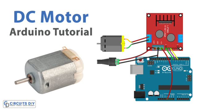 DC Motor Interface with Arduino
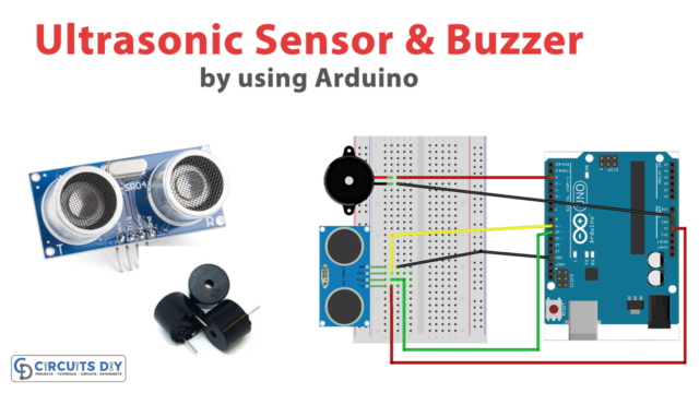 Ultrasonic Sensor with Buzzer using Arduino
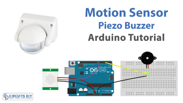 Motion Sensor with Piezo Buzzer - Arduino Tutorial
 Control 28BYJ-48 Stepper Motor with ULN2003 Driver
 BME280 Temperature, Humidity, and Pressure Sensor Module with Arduino
 How to generate Super Mario Theme Song by using Arduino Microcontroller