Introduction
Measuring distance using an Arduino UNO with an ultrasonic sensor HC-SR04 and a buzzer is a fascinating project that involves using an electronic device to detect the distance of an object and provide an audible indication of that distance. The HC-SR04 is an inexpensive and commonly used ultrasonic sensor that measures distance by sending out a sound wave and measuring the time it takes for the wave to bounce back. This project can be a great introduction to the world of electronics and programming, as it involves using various components to build a functional system that interacts with the physical world.
The HC-SR04 ultrasonic sensor is a device that utilizes ultrasonic sound waves to measure distances. It consists of a piezoelectric transducer that serves as both the emitter and receiver of ultrasonic signals. The transducer operates by converting electrical energy into ultrasonic sound waves that are emitted through a dome-shaped transducer face. When the sound waves encounter an object, they reflect back to the transducer, which then converts them back into an electrical signal.
Hardware Components
You will require the following hardware for Ultrasonic Sensor with Buzzer.
| Components | Value | Qty |
|---|---|---|
| Arduino UNO | – | 1 |
| Ultrasonic Sensor | HC-SR04 | 1 |
| Buzzer | – | 1 |
| Breadboard | – | 1 |
| Jumper Wires | – | 1 |
Arduino Code
Step 1: Declare Pin Variables
The first step is to declare integer variables for the trig pin, echo pin, and LED pin. In this code, trigPin is connected to pin 9, echoPin is connected to pin 10, and led is connected to pin 7.
int trigPin = 9;
int echoPin = 10;
int led = 7;
Step 2: Initialize Serial Communication and Set Pin Modes
In the setup() function, serial communication is initialized with a baud rate of 9600 using Serial.begin(9600). Then, the trigPin is set as an output, and echoPin is set as an input using pinMode() function. Additionally, the LED pin is set as an output using pinMode() function.
void setup() {
  Serial.begin(9600);
  pinMode(led, OUTPUT);
  pinMode(trigPin, OUTPUT);
  pinMode(echoPin, INPUT);
}
Step 3: Measure Distance with Ultrasonic Sensor
In the loop() function, the distance is measured with the ultrasonic sensor. First, the duration and distance variables are declared as long integers. Then, the trigger pin is set to high for a short duration using digitalWrite(trigPin, HIGH) and delayMicroseconds(1000). Next, the trigger pin is set back to low using digitalWrite(trigPin, LOW).
The pulseIn() function is used to measure the duration of the reflected pulse on the echo pin. The function waits for the pulse to start and returns the duration in microseconds. The duration variable is set to this duration.
void loop() {
  long duration, distance;
  digitalWrite(trigPin, HIGH);
  delayMicroseconds(1000);
  digitalWrite(trigPin, LOW);
  duration = pulseIn(echoPin, HIGH);
Step 4: Calculate Distance in Centimeters
Once the duration of the pulse is known, the distance can be calculated using the speed of sound. The distance variable is calculated by dividing the duration by 2 (because the pulse has to travel to the object and back) and then dividing by the speed of sound in air, which is approximately 29.1 microseconds per centimeter.
distance = (duration/2) / 29.1;
Step 5: Print Distance to Serial Monitor
The distance measurement is printed to the serial monitor using Serial.print() and Serial.println(). The delay() function is used to introduce a small delay before the next measurement.
Serial.print(distance);
  Serial.println("CM");
  delay(10);
Step 6: Turn On/Off LED/buzzer Based on Distance
The if statement checks if the measured distance is less than or equal to 10 cm. If it is, the LED pin is set to high, which turns on the LED/buzzer. If the measured distance is greater than 10 cm, the else if statement turns off the LED/buzzer by setting the LED/buzzer pin to low.
if (distance <= 10) {
    digitalWrite(led, HIGH);
  } else if (distance > 10) {
    digitalWrite(led, LOW);
  }
}
Schematic
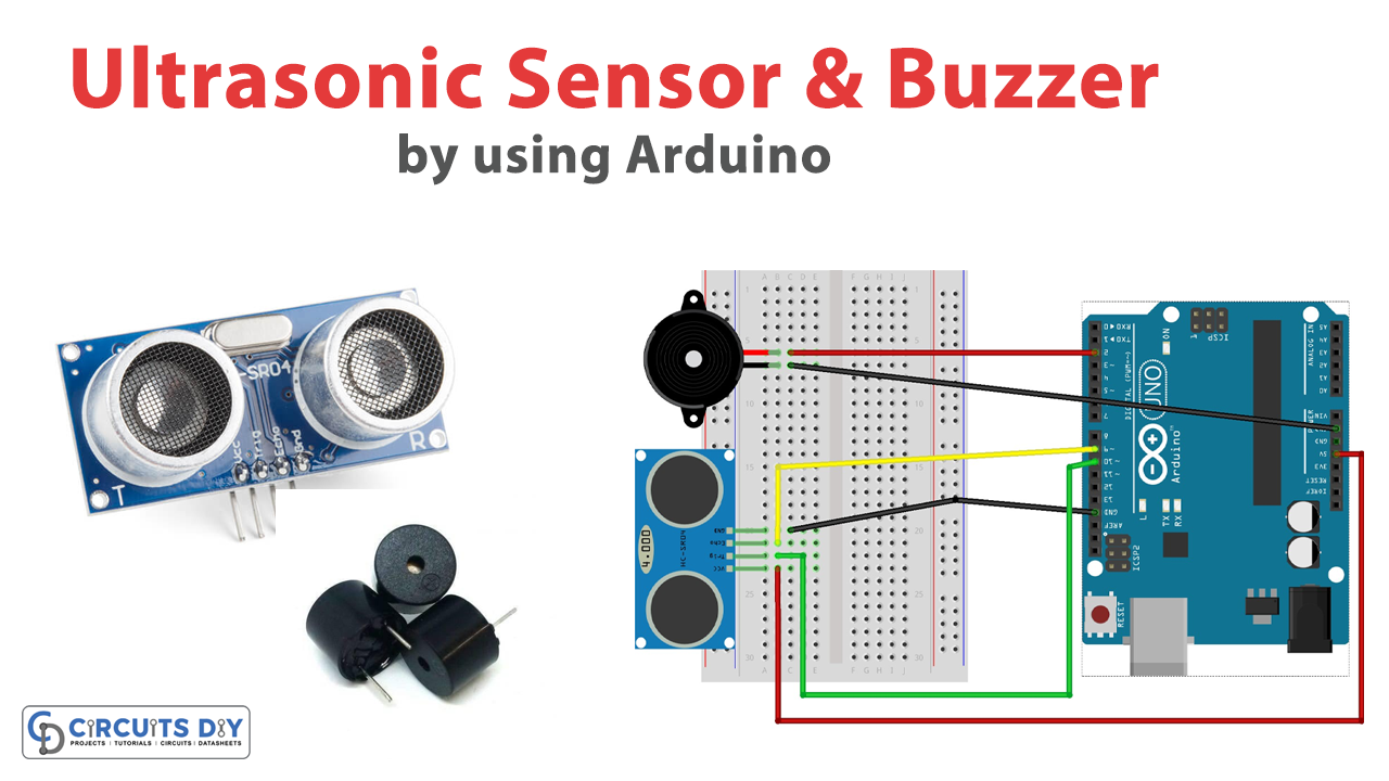
Make connections according to the circuit diagram given below.
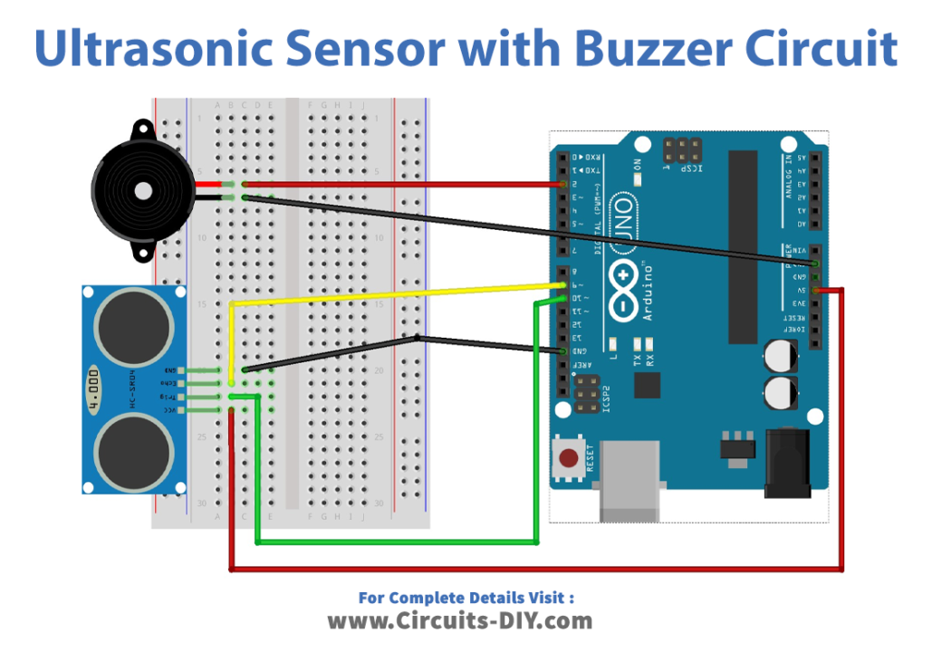
Wiring / Connections
| Arduino | Ultrasonic Sensor | Buzzer |
|---|---|---|
| 5V | VCC | |
| GND | GND | Negative (-) |
| D9 | ECHO | |
| D10 | TRIG | |
| D2 | Positive(+) |
Installing Arduino IDE
First, you need to install Arduino IDE Software from its official website Arduino. Here is a simple step-by-step guide on “How to install Arduino IDE“.
Code
Now copy the following code and upload it to Arduino IDE Software.
int trigPin = 9;
int echoPin = 10;
int led = 7;

void setup() {
  Serial.begin(9600);
  pinMode(led, OUTPUT);
  pinMode(trigPin, OUTPUT);
  pinMode(echoPin, INPUT);
}

void loop() {
  long duration, distance;
  digitalWrite(trigPin, HIGH);
  delayMicroseconds(1000);
  digitalWrite(trigPin, LOW);
  duration = pulseIn(echoPin, HIGH);
  distance = (duration/2) / 29.1;
  Serial.print(distance);
  Serial.println("CM");
  delay(10);
  if (distance <= 10) {
    digitalWrite(led, HIGH);
  } else if (distance > 10) {
    digitalWrite(led, LOW);
  }
}
Working Explanation
In the setup() function, the serial communication is initiated with a baud rate of 9600. The pin modes for the LED, trigPin, and echoPin are set to output, output, and input respectively. In the loop() function, a duration variable and a distance variable are defined as long data type. The trigPin is set to HIGH for 1 millisecond and then set to LOW. The pulseIn() function measures the duration of the pulse received on the echoPin and stores it in the duration variable. The distance variable is then calculated based on the duration of the pulse using the speed of sound. The distance is then printed to the serial monitor along with the unit “CM”.
The LED is controlled based on the distance measured. If the distance is less than or equal to 10cm, the LED is turned on by setting the led/buzzer pin to HIGH. Otherwise, the LED is turned off by setting the led/buzzer pin to LOW. The delay() function is used to add a delay of 10 milliseconds between measurements.
Applications
- Obstacle avoidance systems
- Parking assist systems
- Security systems
- Industrial automation
- Robotics