Introduction
A Hall effect sensor is an electronic device that detects the Hall effect and converts its findings into electronic data, which can then be used to either switch a circuit on and off, offer a measurement of a fluctuating magnetic field, or be processed by an embedded computer, or be displayed on an interface. In this tutorial, we are going to Make an “Interface MLX90393 Digital Hall Sensor Module with Arduino”
MLX90393 Digital Hall Sensor
The MLX90393 module is a potent, adaptable, incredibly compact, universal 3D hall effect sensor module that fits easily into any do-it-yourself applications that need 3D position detection. With a resolution rate of 0.161uT and a maximum full-scale resolution of 44,000uT, it uses just 100uA of current. In about size, it has an incredibly strong magnetic field sensing capability that can detect even the smallest magnetic fields with ease and transmits the information via the SPI and I2C protocols. It functions as a compass sensor but also functions as a linear actuator position sensor, a flow meter with a magnetic impeller, and a non-contact controller.
Features and Specifications
- Operating Voltage: 2.2 – 3.6 Volts
- Sink/Source Current: 100 uA
- Operating Temperature: -200C – 850C
- 16-bit ADC Resolution: 0.161 uT
- Full-Scale Resolution: 44,000 uT
- 12C Address: 0xC0
- Serial Communication Data Rate: 10 MHz
- XYZT Triple-axial Position Output
- Dimensions(LxWxH): 26mm x 26.3mm x 5mm
Pinouts
| Pin Number | Pin Name | Descriptions |
| 1 | CS | SPI Chip select |
| 2 | MISO | SPI MISO (Master IN Slave Out) |
| 3 | MOSI | SPI MOSI (Master Out Slave In) |
| 4 | SCLK | SPI Clock input |
| 5 | 3.3V | 3.3V Input |
| 6 | GND | Power supply ground |
| 7 | GND | Power supply ground |
| 8 | 3.3V | 3.3V Input |
| 9 | SDA | I2C serial data (SDA) |
| 10 | SCL | I2C serial clock (SCL) |
| 11 | INT | Interrupt Pin |
| 12 | TRIG | TRIGGER Pin |
Hardware Required
| S.no | Components | Value | Qty |
|---|---|---|---|
| 1 | Arduino UNO | – | 1 |
| 2 | USB Cable Type A to B | – | 1 |
| 3 | Digital Hall Sensor | MLX90393 | 1 |
| 4 | Jumper Wires | – | – |
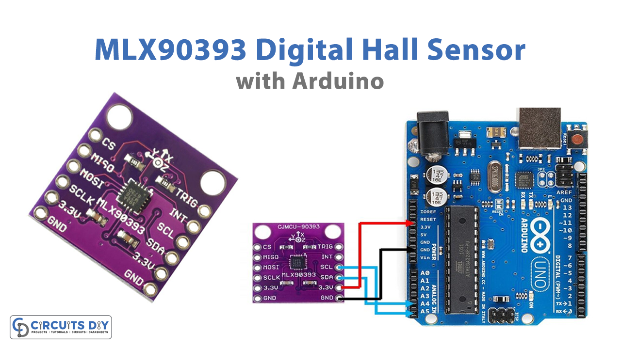
Circuit Diagram

Connection Table
| Arduino UNO | MLX90393 Digital Hall Sensor |
|---|---|
| GND | GND |
| 3.3v | Vcc |
| A4 | SDA |
| A5 | SCL |
Arduino Code
#include<Wire.h>

// MLX90393 I2C Address is 0x0C(12)
#define Addr 0x0C

void setup()
{
// Initialise I2C communication as MASTER
Wire.begin();
// Initialise serial communication, set baud rate = 9600
Serial.begin(9600);

// Start I2C Transmission
Wire.beginTransmission(Addr);
// Select Write register command
Wire.write(0x60);
// Set AH = 0x00, BIST disabled
Wire.write(0x00);
// Set AL = 0x5C, Hall plate spinning rate = DEFAULT, GAIN_SEL = 5
Wire.write(0x5C);
// Select address register, (0x00 << 2)
Wire.write(0x00);
// Stop I2C Transmission
Wire.endTransmission();

// Request 1 byte of data
Wire.requestFrom(Addr, 1);

// Read status byte
if(Wire.available() == 1)
{
unsigned int c = Wire.read();
}

// Start I2C Transmission
Wire.beginTransmission(Addr);
// Select Write register command
Wire.write(0x60);
// Set AH = 0x02
Wire.write(0x02);
// Set AL = 0xB4, RES for magnetic measurement = 0
Wire.write(0xB4);
// Select address register, (0x02 << 2)
Wire.write(0x08);
// Stop I2C Transmission
Wire.endTransmission();

// Request 1 byte of data
Wire.requestFrom(Addr, 1);

// Read status byte
if(Wire.available() == 1)
{
unsigned int c = Wire.read();
}
delay(300);
}

void loop()
{
unsigned int data[7];

// Start I2C Transmission
Wire.beginTransmission(Addr);
// Start single meaurement mode, ZYX enabled
Wire.write(0x3E);
// Stop I2C Transmission
Wire.endTransmission();

// Request 1 byte of data
Wire.requestFrom(Addr, 1);

// Read status byte
if(Wire.available() == 1)
{
unsigned int c = Wire.read();
}
delay(100);

// Start I2C Transmission
Wire.beginTransmission(Addr);
// Send read measurement command, ZYX enabled
Wire.write(0x4E);
// Stop I2C Transmission
Wire.endTransmission();

// Request 7 bytes of data
Wire.requestFrom(Addr, 7);

// Read 7 bytes of data
// status, xMag msb, xMag lsb, yMag msb, yMag lsb, zMag msb, zMag lsb
if(Wire.available() == 7);
{
data[0] = Wire.read();
data[1] = Wire.read();
data[2] = Wire.read();
data[3] = Wire.read();
data[4] = Wire.read();
data[5] = Wire.read();
data[6] = Wire.read();
}

// Convert the data
int xMag = data[1] * 256 + data[2];
int yMag = data[3] * 256 + data[4];
int zMag = data[5] * 256 + data[6];

// Output data to serial monitor
Serial.print("Magnetic Field in X-Axis : ");
Serial.println(xMag);
Serial.print("Magnetic Field in Y-Axis : ");
Serial.println(yMag);
Serial.print("Magnetic Field in Z-Axis : ");
Serial.println(zMag);
delay(500);
}
Working Explanation
To Interface MLX90393 Digital Hall Sensor Module with Arduino, connect the circuit according to the diagram, and upload the code in Arduino. Open the Serial monitor. By monitoring the magnetic field strength, it will show the module’s position in all three dimensions at that specific moment. Adjust the module by moving it along one or more dimensions. The updated position of the module will be seen in the serial monitor.
Code Explanation
- Download the library for the MLX90393 module in the Arduino IDE Include the relevant library in the code.
- The void setup loop initializes the Serial monitor and I2C transmission as connections are formed to interact via the I2C interface. Set up the data’s read and write instructions.
- When the status byte is set to high, the chip will read data. The data is written into the registers as soon as the 8-bit data has been read. A 9600 baud rate Serial monitor is used to show the data once it has been translated to decimal code.
Application and Uses
- Joysticks
- Consumer electronic devices
- Navigation systems
- Robotics applications, Etc.