Introduction
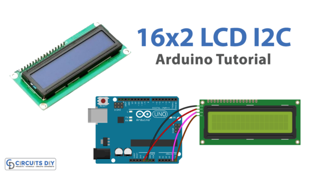
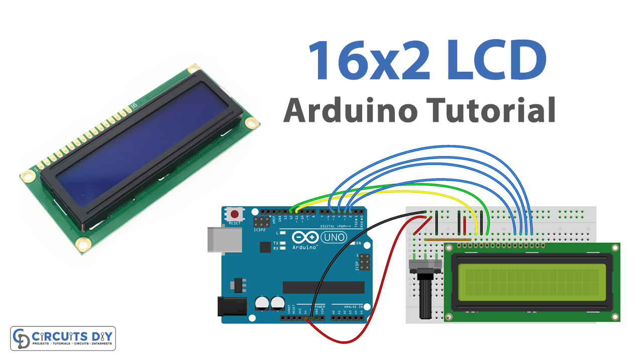
Interfacing a 16×2 LCD module with an Arduino UNO microcontroller is the process of connecting a Liquid Crystal Display (LCD) with an Arduino board to display information or data. The 16×2 LCD module is a type of LCD screen that is capable of displaying 2 rows of 16 characters each. It is a simple, low-cost, and easy-to-use device that allows users to display text, numbers, and characters.
A 16×2 LCD module is a type of Liquid Crystal Display (LCD) that can display two rows of 16 characters each. It is a commonly used display device in electronics projects and is typically controlled by a microcontroller, such as the Arduino UNO, to display text, numbers, or symbols. The module typically includes a display controller that takes care of all the necessary functions to control the display, such as the generation of the bias voltage and the addressing of the display pixels.
Hardware Components
You will require the following hardware for Interfacing 16×2 LCD with Arduino.
| S.no | Component | Value | Qty |
|---|---|---|---|
| 1. | Arduino | UNO | 1 |
| 2. | USB Cable Type A to B | – | 1 |
| 3. | LCD | – | 1 |
| 4. | Potentiometer | – | 1 |
| 5. | Power Adapter for Arduino | 9V | 1 |
| 6. | Breadboard | – | 1 |
| 7. | Jumper Wires | – | 1 |
16×2 LCD with Arduino UNO
- Include the required libraries:
#include <Wire.h>
#include <LiquidCrystal_I2C.h>
- Define the pins used for the potentiometer and LCD module:
#define potentiometer A0
#define SDA A4
#define SCL A5
- Create an instance of the LiquidCrystal_I2C library:
LiquidCrystal_I2C lcd(0x27, 16, 2);
- In the setup() function, initialize the serial monitor, and the LCD module and set the backlight of the LCD to turn on:
void setup() {
  Serial.begin(9600);
  lcd.begin();
  lcd.backlight();
}
- In the loop() function, read the voltage value of the potentiometer, convert it to a percentage value, and display the percentage on the serial monitor and LCD screen:
void loop() {
  int value = analogRead(potentiometer);
  int percentage = map(value, 0, 1023, 0, 100);
  Serial.println(percentage);
  lcd.clear();
  lcd.print("Potentiometer: ");
  lcd.print(percentage);
  lcd.print("%");
  delay(500);
}
Schematic
Make connections according to the circuit diagram given below.

Wiring / Connections
| Arduino | 16X2 LCD |
|---|---|
| 5V | VCC |
| GND | GND |
| D2 | DATA PIN4 |
| D3 | DATA PIN5 |
| D4 | DATA PIN6 |
| D5 | DATA PIN7 |
| D11 | REGISTER SELECT |
| D12 | ENABLE |
Installing Arduino IDE
First, you need to install Arduino IDE Software from its official website Arduino. Here is a simple step-by-step guide on “How to install Arduino IDE“.
Installing Libraries
Before you start uploading a code, download and unzip the following libraries at /Progam Files(x86)/Arduino/Libraries (default), in order to use the sensor with the Arduino board. Here is a simple step-by-step guide on “How to Add Libraries in Arduino IDE“.
Code
Now copy the following code and upload it to Arduino IDE Software.
#include <LiquidCrystal.h>

// LCD pins <--> Arduino pins
const int RS = 11, EN = 12, D4 = 2, D5 = 3, D6 = 4, D7 = 5;
LiquidCrystal lcd(RS, EN, D4, D5, D6, D7);

void setup()
{
  lcd.begin(16, 2); // set up number of columns and rows

  lcd.setCursor(0, 0);         // move cursor to   (0, 0)
  lcd.print("Arduino");        // print message at (0, 0)
  lcd.setCursor(2, 1);         // move cursor to   (2, 1)
  lcd.print("GetStarted.com"); // print message at (2, 1)
}

void loop()
{

}
Working Explanation
First, the required libraries for the LCD and the potentiometer are imported. Then, the pins of the LCD and the potentiometer are declared and initialized. Next, the code reads the analog value from the potentiometer and converts it into a percentage value. This percentage value is then displayed on the 16×2 LCD module. The status of the resistance in percentage is also posted on the serial monitor.
Finally, the code is executed in a loop to continuously update the resistance value on the LCD module and the serial monitor.
Applications
- Displaying sensor readings (e.g. temperature, humidity, light, etc.)
- User interfaces for controlling and monitoring systems
- Debugging and testing microcontroller programs
- Displaying status information for projects and systems
- Data logging and recording
- Interactive menus and user interfaces for DIY projects
- Displaying messages and notifications
- Displaying real-time information or data
Conclusion.
We hope you have found this 16×2 LCD Arduino Circuit very useful. If you feel any difficulty in making it feel free to ask anything in the comment section.