Introduction
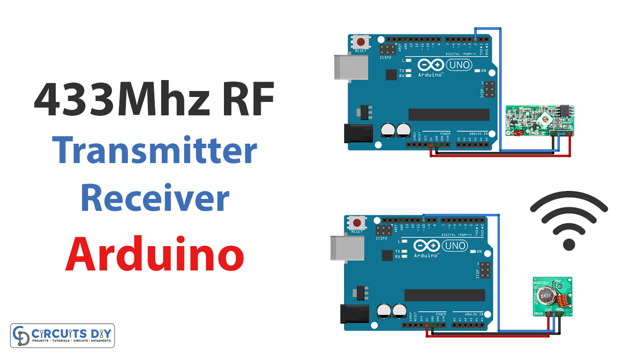
This blog is about “Interfacing 315/433 MHz RF Transmitter-Receiver Module with Arduino.”
The world of technology is constantly evolving and expanding, and one exciting area is radio frequency (RF) communication. RF technology allows for the transmission of data wirelessly over the airwaves. It has many applications, from cell phones and wifi to remote control devices and even satellite communication.
One handy tool in the RF world is the 315/433 MHz RF transmitter-receiver module, which you can use in conjunction with an Arduino microcontroller to create all kinds of wireless projects and devices. Whether you’re a beginner looking to get your feet wet in the sea of RF communication or an experienced engineer looking to add an RF module to your project, the 315/433 MHz RF transmitter-receiver module is an incredibly versatile and practical device to have at your disposal. So let’s dive in and explore the exciting module.
What are RF Transmitter-Receiver Modules?
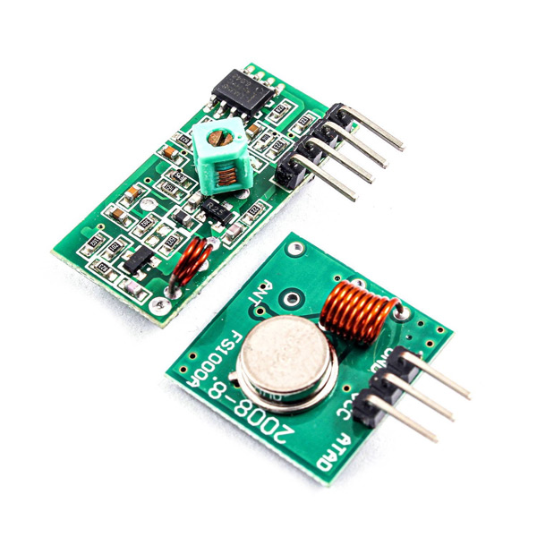
The radio frequency (RF) transmitter and receiver modules are tiny electronic modules that send and receive radio signals between two devices. The transmitter and receiver modules are at the heart of this wireless magic device. The transmitter module sends a signal, carrying data from one device to another. On the other end, the receiver module patiently waits for that signal to arrive so it can decode the data it contains.
Hardware Components
You will require the following hardware for Interfacing the 315/433 MHz RF Transmitter-Receiver Module with Arduino.
| S.no | Component | Value | Qty |
|---|---|---|---|
| 1. | Arduino UNO | – | 1 |
| 2. | TRANSMITTER AND RECEIVER | 433MHz RF | 1 |
| 3. | TRANSMITTER AND RECEIVER | 315MHz RF | 1 |
| 4. | Breadboard | – | 1 |
| 5. | Jumper Wires | – | 1 |
RF Transmitter-Receiver Module with Arduino
Here are the steps you can follow to interface a 315/433 MHz RF transmitter-receiver module with an Arduino:
Schematic
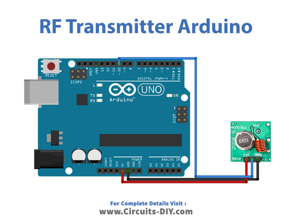
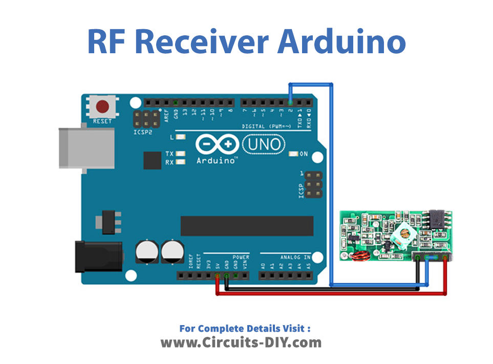
Make connections according to the circuit diagram given below.
Wiring / Connections
| Arduino | RECEIVER Sensor | TRANSMITTER Sensor |
|---|---|---|
| 5V | VCC | VCC |
| GND | GND | GND |
| D2 | Data | |
| D10 | DATA |
Installing Arduino IDE
First, you need to install Arduino IDE Software from its official website Arduino. Here is a simple step-by-step guide on “How to install Arduino IDE.”
Installing Libraries
Before you start uploading a code, download and unzip the following libraries at /Progam Files(x86)/Arduino/Libraries (default), in order to use the sensor with the Arduino board. Here is a simple step-by-step guide on “How to Add Libraries in Arduino IDE“.
Code
Now copy the following code and upload it to Arduino IDE Software.
Transmitter
/*
  Example for different sending methods

  https://github.com/sui77/rc-switch/

*/

#include <RCSwitch.h>

RCSwitch mySwitch = RCSwitch();

void setup() {

  Serial.begin(9600);

  // Transmitter is connected to Arduino Pin #10
  mySwitch.enableTransmit(10);

  // Optional set protocol (default is 1, will work for most outlets)
  // mySwitch.setProtocol(2);

  // Optional set pulse length.
  // mySwitch.setPulseLength(320);

  // Optional set number of transmission repetitions.
  // mySwitch.setRepeatTransmit(15);

}

void loop() {

  /* See Example: TypeA_WithDIPSwitches */
  mySwitch.switchOn("11111", "00010");
  delay(1000);
  mySwitch.switchOff("11111", "00010");
  delay(1000);

  /* Same switch as above, but using decimal code */
  mySwitch.send(5393, 24);
  delay(1000);
  mySwitch.send(5396, 24);
  delay(1000);

  /* Same switch as above, but using binary code */
  mySwitch.send("000000000001010100010001");
  delay(1000);
  mySwitch.send("000000000001010100010100");
  delay(1000);

  /* Same switch as above, but tri-state code */
  mySwitch.sendTriState("00000FFF0F0F");
  delay(1000);
  mySwitch.sendTriState("00000FFF0FF0");
  delay(1000);

  delay(20000);
}
Receiver
/*
  Simple example for receiving

  https://github.com/sui77/rc-switch/
*/

#include <RCSwitch.h>

RCSwitch mySwitch = RCSwitch();

void setup() {
  Serial.begin(9600);
  mySwitch.enableReceive(0);  // Receiver on interrupt 0 => that is pin #2
}

void loop() {
  if (mySwitch.available()) {

    int value = mySwitch.getReceivedValue();

    if (value == 0) {
      Serial.print("Unknown encoding");
    } else {
      Serial.print("Received ");
      Serial.print( mySwitch.getReceivedValue() );
      Serial.print(" / ");
      Serial.print( mySwitch.getReceivedBitlength() );
      Serial.print("bit ");
      Serial.print("Protocol: ");
      Serial.println( mySwitch.getReceivedProtocol() );
    }

    mySwitch.resetAvailable();
  }
}
Let’s Test It
Once the RF module and microcontroller or development board are set up, you can upload a sketch that will allow you to send and receive data using the RF module. Open the serial monitor, and it will show the received data.
Working Explanation
Let’s explore the codes of both sides (transmitter and receiver) in order to understand the working of the entire circuit.
Transmitter
- This code uses the RCSwitch library to control remote switches using an Arduino board. The RCSwitch object, mySwitch, is created at the beginning of the code, and its transmit function is enabled in the void setup function using pin 10. The void loop function then sends various signals to control the remote switches, with a delay between each action.
- Several optional settings can be configured for the mySwitch object, such as the protocol to use, the pulse length, and the number of transmission repetitions. These settings can be adjusted using the setProtocol, setPulseLength, and setRepeatTransmit functions.
- The switchOn and switchOff functions turn the remote switch on and off, respectively. The send function turns the remote switch on and off using decimal or binary code. The sendTriState function uses a “tri-state” code to control the remote switch.
Receiver
- This code also uses the RCSwitch library to receive wireless signals using an Arduino board.
- The RCSwitch object, called mySwitch, is created and configured in the setup function. The receiver is connected to Arduino Pin 2.
- In the loop function, the code checks if a signal is available using the mySwitch.available function. If a signal is received, the code gets the received value, bit length, and protocol using the getReceivedValue, getReceivedBitlength, and getReceivedProtocol functions, respectively. These values are then printed to the serial monitor using the Serial.print function. If the received value is 0, it means that the encoding is unknown.
- In the end, the code resets the availability of the received signal using the resetAvailable function to receive new signals in the next iteration of the loop function.
Applications
- RF controlled toys
- Remote control systems and devices
- Wireless automation, etc
Conclusion.
We hope you have found this Interfacing 315/433 MHz RF Transmitter-Receiver Module with Arduino Circuit very useful. If you feel any difficulty making it feel free to ask anything in the comment section.