Introduction
Solar energy is an excellent source of renewable energy that can be used to power homes, businesses, and other applications. However, the amount of energy that can be generated by a solar panel depends on the amount of sunlight it receives. This is where a single-axis solar tracker using Arduino UNO, LDR, and servo motor comes in.
By automatically adjusting the position of the solar panel to face the sun throughout the day, a single-axis solar tracker can significantly increase the amount of energy that can be generated by a solar panel. This cost-effective and efficient system is becoming increasingly popular as more people look for ways to make their solar energy systems more effective and sustainable.
Hardware Components
You will require the following hardware Solar Tracker Project.
| Components | Value | Qty |
|---|---|---|
| Arduino UNO | – | 1 |
| Servo Motor | – | 2 |
| LDR | – | 2 |
| Resistor | Ω | 2 |
| Solar Panel | ||
| Breadboard | – | 1 |
| Jumper Wires | – | 1 |
Code Explanation
- Include the Servo library:
#include <Servo.h>This line includes the Servo library, which provides functions for controlling servo motors.
- Create an instance of the Servo class:
Servo sg90;This creates an instance of the Servo class called sg90.
- Define the initial position of the servo motor:
int initial_position = 90This sets the initial position of the servo motor to 90 degrees.
- Define the pins for the LDRs and the servo motor:
int LDR1 = A0;
int LDR2 = A1;
int servopin = 9;
This defines the pins for LDR1 and LDR2 as the analog input pins A0 and A1, respectively. The servopin is set to pin 9, which is a PWM (Pulse Width Modulation) pin used for controlling the servo motor.
- Set up the servo motor in the
setup()function:
void setup() {
  sg90.attach(servopin);
  pinMode(LDR1, INPUT);
  pinMode(LDR2, INPUT);
  sg90.write(initial_position);
  delay(2000);
}
In the setup() function, we attach the sg90 servo motor to the servopin and set the pins for LDR1 and LDR2 as inputs. The sg90.write(initial_position) sets the initial position of the servo motor to 90 degrees. The delay(2000) function pauses the program for 2 seconds to give time for the servo motor to settle into its initial position.
- Read the LDR values and adjust the servo motor position in the
loop()function:
void loop() {
  int R1 = analogRead(LDR1);
  int R2 = analogRead(LDR2);
  int diff1 = abs(R1 - R2);
  int diff2 = abs(R2 - R1);

  if ((diff1 <= error) || (diff2 <= error)) {
    // do nothing if the difference between the LDR readings is within the error tolerance
  } else {
    if (R1 > R2) {
      initial_position = -initial_position; // change the direction of the servo motor
    }
    if (R1 < R2) {
      initial_position = ++initial_position; // move the servo motor position one degree to the right
    }
  }

  sg90.write(initial_position);
  delay(100);
}
Schematic
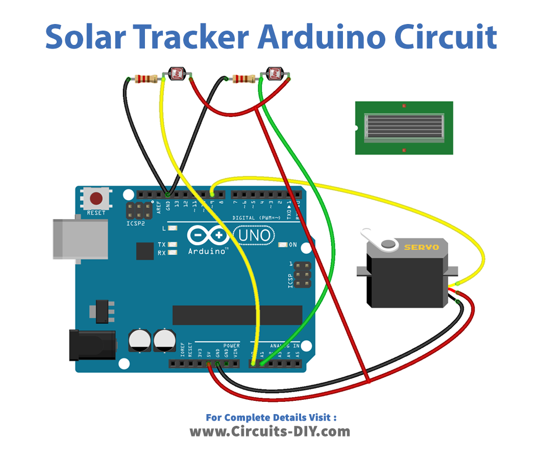
Make connections according to the circuit diagram given below.
Wiring / Connections
| Arduino | Servo Motor | LDRs |
|---|---|---|
| 5V | 5V | |
| GND | GND | GND |
| D9 | PWM | |
| A0 | LDR 1 + Resistor | |
| A1 | LDR 2 + Resistor |
Installing Arduino IDE
First, you need to install Arduino IDE Software from its official website Arduino. Here is a simple step-by-step guide on “How to install Arduino IDE“.
Installing Libraries
Before you start uploading a code, download and unzip the following libraries at /Progam Files(x86)/Arduino/Libraries (default), in order to use the sensor with the Arduino board. Here is a simple step-by-step guide on “How to Add Libraries in Arduino IDE“.
Code
Now copy the following code and upload it to Arduino IDE Software.
#include <Servo.h>

//including the library of servo motor
Servo sg90;
int initial_position = 90;
int LDR1 = A0; //connect The LDR1 on Pin A0
int LDR2 = A1; //Connect The LDR2 on pin A1
int error = 5;
int servopin=9; //You can change servo just makesure its on arduino’s PWM pin
void setup()
{

sg90.attach(servopin);
pinMode(LDR1, INPUT);
pinMode(LDR2, INPUT);
sg90.write(initial_position); //Move servo at 90 degree
delay(2000);
}

void loop()
{
int R1 = analogRead(LDR1); // read LDR 1
int R2 = analogRead(LDR2); // read LDR 2
int diff1= abs(R1 – R2);
int diff2= abs(R2 – R1);

if((diff1 <= error) || (diff2 <= error)) {

} else {
if(R1 > R2)
{
initial_position = –initial_position;
}
if(R1 < R2)
{
initial_position = ++initial_position;
}
}
sg90.write(initial_position);
delay(100);
}
Working Explanation
The program starts by including the Servo library to control the servo motor. Then, it defines the pin numbers for LDR1 and LDR2, sets the error tolerance, and the PWM pin number for the servo motor.
In the setup() function, it attaches the servo motor to the specified pin and sets its initial position to 90 degrees. Then, it waits for 2 seconds before moving on to the loop() function. The loop() function reads the values of LDR1 and LDR2 using the analogRead() function and calculates the difference between the readings. If the difference is within the error tolerance, the servo motor does not move. Otherwise, it adjusts its position based on the LDR readings.
If LDR1 has a higher reading than LDR2, it changes the servo motor’s position to the opposite direction, and vice versa if LDR2 has a higher reading. The abs() function is used to calculate the absolute difference between the two LDR readings.
Applications
- Residential solar power systems
- Commercial solar power systems
- Agricultural applications

