Introduction
Electrically erasable programmable read-only memory, or EEPROM for short, is a form of non-volatile memory found in computers and microcontrollers used in smart cards, etc. Because they are compact electronics in compact packaging, EEPROMs are also relatively affordable. To learn how to interface EEPROM with a microcontroller, n this tutorial, we will do “24LC1026 Serial EEPROM Interfacing with Arduino”
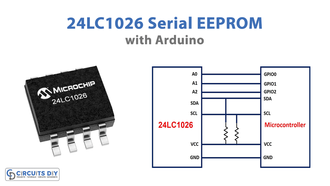
24LC1026 Serial EEPROM
The 24LC1026 is an 8-pin EEPROM integrated circuit. So, much like a pen drive, we may store the information on this IC and it will stay there even after the power is switched off. The data can then be recovered or overwritten as needed. This IC supports Serial, 2-Wire, and I2C interfaces, making it simple to connect with most MCUs and consuming fewer pins The 24LC1026 was designed for high-performance, low-power applications, and supports byte and page writes of up to 128 bytes of data.
Features and Specifications
- Maximum Clock Frequency: 400 kHz
- 128-Byte Page Write Buffer
- Page Write Time 5mS Max.
- Read current 450 uA, max.
- Standby current 5 uA, max.
- Supply Current – Max: 5 mA
- Supply Voltage – Min: 2.5V
- Supply Voltage – Max: 5.5 V
- Operating voltage: 2.5V to 5.5V
- Organisation:128 k x 8
- Communication: Serial, 2-Wire, I2C
- Write cycle time: 5ms
- 16-byte Page (4K) Write Modes
Hardware Required
| S.no | Component | Value | Qty |
|---|---|---|---|
| 1. | Arduino UNO | – | 1 |
| 2. | USB Cable Type A to B | – | 1 |
| 3. | Serial EEPROM | 24LC1026 | 1 |
| 4. | Jumper Wires | – | – |
Circuit Diagram

Connection Table
| Arduino UNO | 24LC1026 Serial EEPROM |
|---|---|
| GND | GND |
| 3.3v | Vcc |
| SDA | SDA |
| SCL | SCL |
| A0 | GPIO-0 |
| A1 | GPIO-1 |
| A2 | GPIO-2 |
Interfacing with Arduino
The Serial Clock pin, i.e.; pin 6 is connected to the microcontroller’s SCK pin, while pin 5 which is the Serial Data pin is connected to the microcontroller’s SDA pin. Two pull-up resistors are used to pull the SCK and SDA pins high. This will maintain the bus in a high state when it is idling. The three pins are linked to the GPIO pins through chip-select pins A0, A1, and A2. Chip-select pins are only necessary if more than one I2C device or EEPROM is attached to the same microcontroller; otherwise, three pins can be directly grounded.
When voltage is applied to the hardware WP, it becomes operational. It safeguards the entire memory array against data loss. It must be maintained low to execute regular read and write functions; otherwise, it permits data and addresses to be read-only and prohibits write operations.
The communication begins with the transfer of the address of the device to the EEPROM, followed by the memory address. Following the allocation of addresses, data is sent and stored at the chosen place. When data must be read, requests with the given device and memory address are submitted. The EEPROM then returns the data.
Application and Uses
- Audio devices
- Storage devices
- Different communication devices, Etc