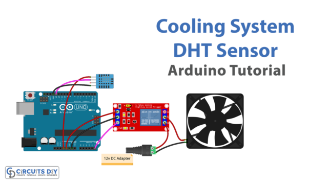
In this tutorial, we are going to make an “Arduino DAC Tutorial”.
A DAC (Digital to Analog Converter) is a circuit, that allows you to translate numeric values into analog signals. So you can have variable output voltages, from 0 to 5V by setting only a variable. If you want to do this with an Arduino, you will need to use an external chip. Here DAC IC MCP4725-based breakout board is used, it is a 12-Bit Digital-to-Analog Converter with EEPROM memory. This IC utilizes low power and gives high-accuracy output. It comes in a sot package, hence better to go with the breakout board.
In this tutorial, we used the Sparkfun I2C breakout MCP4725 board. By using this board, we can obtain Analog voltage from the Arduino board (depending on the digital input, and it accepts input in I2C format). With a few components, we can build a DAC circuit. This circuit will do a nice job, in low-speed and low-precision applications. This will work as DAC because you can have output voltages between 0V and 5V, by only modifying a variable between 0 and 255.

MCP4725 DAC IC
MCP4725 IC is a 12-Bit Digital Analog converter module. This IC is used to generate output analog voltages from (0 to 5V), it is controlled by using I2C communication. It also comes with onboard nonvolatile memory EEPROM. This IC provides a 12-bit resolution, which means we can use (0 to 4096) as input. Due to this, it can provide the voltage output with respect to a reference voltage. The maximum reference voltage is 5V. This IC can be addressed by an external A0 address pin and operates in normal or power-down mode. It takes a wide range of input supply voltage (2.7V to 5.5V), from a single supply source. This IC provides eight addresses, through I2C and has an extended temperature range: -40°C to +125°C. It has a fast settling time, around 6µs (typically). And can operate in standard (100 kbps), Fast (400 kbps), and High Speed (3.4 Mbps) modes. It operates in two modes, normal or power-down, and has less power consumption. A list of applications of MCP4725 is listed below, although the commonly used area is where PWM signals can’t be generated, where a sine wave is required, in dealing with audio projects.
Hardware Required
| S.no | Components | Value | Qty |
|---|---|---|---|
| 1 | Arduino UNO | – | 1 |
| 2 | USB Cable Type A to B | – | 1 |
| 3 | DAC I2C | MCP4725 | 1 |
| 4 | Jumper Wires | – | – |
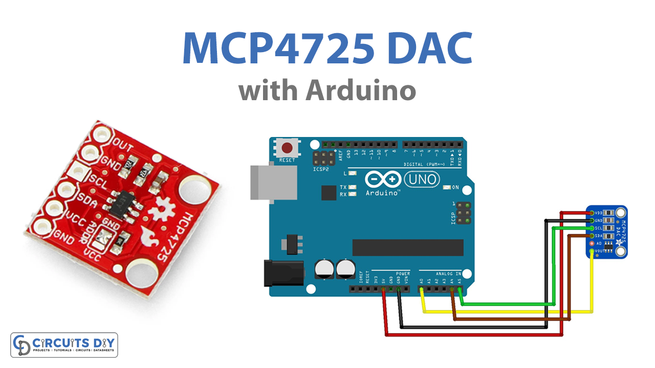
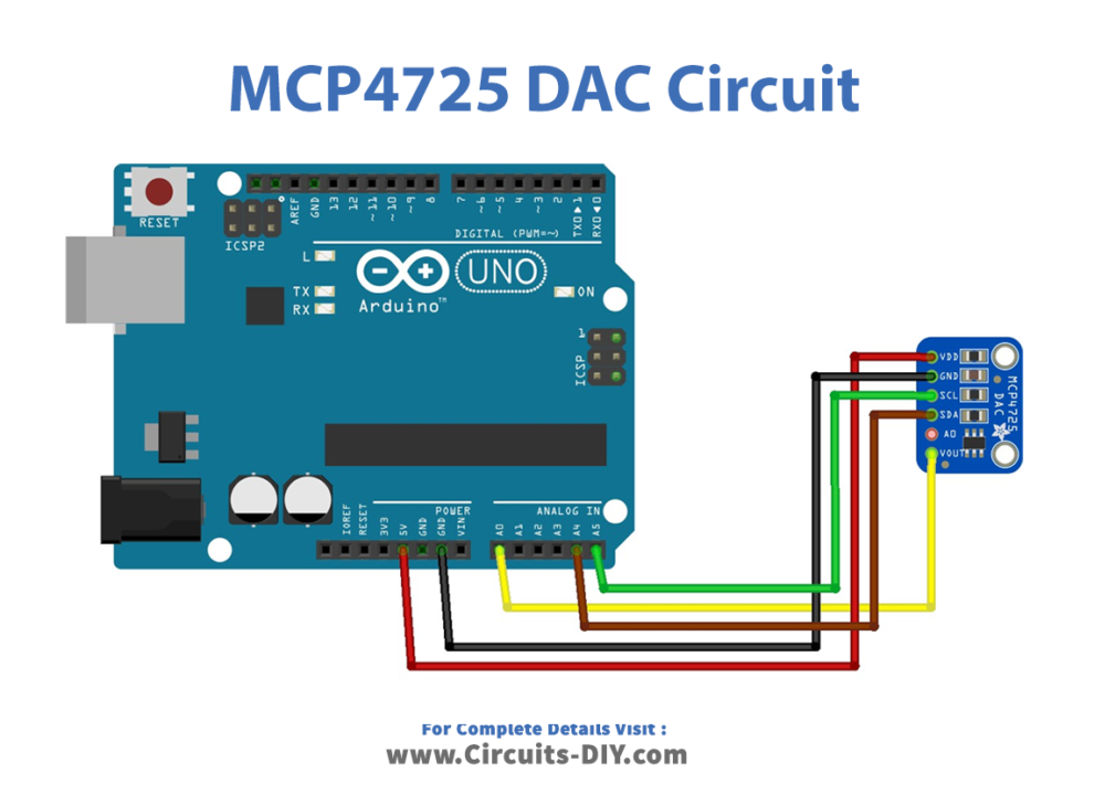
MCP4725 i2c DAC Arduino Interface
Working Explanation
As shown in the circuit, connect Vcc (power) to a 5V power supply. And connect the GND pin of the MCP4725 board to the Ground pin of the Arduino. These two pins power the MCP4725 breakout board. Since the DAC uses I2C, the two-pin interface that can give up to 127 unique sensors attached (each must have a different ADDRESS).
Connect the SDA pin to the I2C Data pin (this is A4). Connect SCL to the I2C Clock pin (this is A5). These two pin connector is for I2C communication. The output pin of MCP4725 is connected with Analog pin A0, by this way we can measure and display the Analog voltage obtained from MCP4725 in a serial monitor. You can also measure by using a digital voltmeter or multimeter. After completing the hookup, upload the following Arduino code and obtain the result (output) on the serial monitor.
Arduino MCP4725 Code
#include <Wire.h>           //wire library
#include <Adafruit_MCP4725.h> // MCP4725 library from adafruit
#define analogVin A0          // Analog voltage input to A0

Adafruit_MCP4725 MCP4725;

void setup(void) {
  Serial.begin(9600);
  MCP4725.begin(0x60); // Default I2C Address of MCP4725 breakout board (sparkfun)

}

void loop(void) {

    uint32_t MCP4725_value;
    int adcValueRead = 0;
    float voltageRead = 0;

    float MCP4725_expected_output;


    for (MCP4725_value = 0; MCP4725_value < 4096; MCP4725_value = MCP4725_value + 15)
    {
      MCP4725_expected_output = (5.0/4096.0) * MCP4725_value;
      MCP4725.setVoltage(MCP4725_value, false);
      delay(250);
      adcValueRead = analogRead(analogVin);
      voltageRead = (adcValueRead * 5.0 )/ 1024.0;

      Serial.print("MCP4725 Value: ");
      Serial.print(MCP4725_value);

      Serial.print("\tExpected Voltage: ");
      Serial.print(MCP4725_expected_output,3);

      Serial.print("\tArduino ADC Value: ");
      Serial.print(adcValueRead);

      Serial.print("\tArduino Voltage: ");
      Serial.println(voltageRead,3);
    }
}
Applications
- Commonly used along with Arduino boards
- Data Acquisition Systems
- Used as DAC for Low Power Portable Instrumentation systems
- To Calibrate Sensors
- Closed-Loop Servo motor control
- Offset Trimming
- Generally used for audio projects and analog projects
- Used in situations where PWM can’t be used
- Used where Sine wave or adjustable bias point is needed
- PC Peripherals