Introduction
An LED blink program without using the delay the function is a program that continuously blinks an LED on and off, without pausing in between blinks. The program works by using the Arduino’s digital output capabilities to control the LED, and by using a variable to store the current state of the LED.
The program can be used for real-time monitoring, timing applications, communication, interactive displays, power conservation, security, entertainment, and scientific experiments. It can also be used for visual effects or as a way to indicate the status of a device or system.
Hardware Components
You will require the following hardware for LED Blink without Delay circuit.
| S.no | Component | Value | Qty |
|---|---|---|---|
| 1. | Arduino UNO | – | 1 |
| 2. | USB Cable Type A to B | – | 1 |
| 3. | Button | – | 1 |
| 4. | LED | – | 1 |
| 5. | Resistor | 220Ω | 1 |
| 6. | 9V Power Adapter for Arduino | – | 1 |
| 7. | Breadboard | – | 1 |
| 8. | Jumper Wires | – | 1 |
LED Blink without Delay
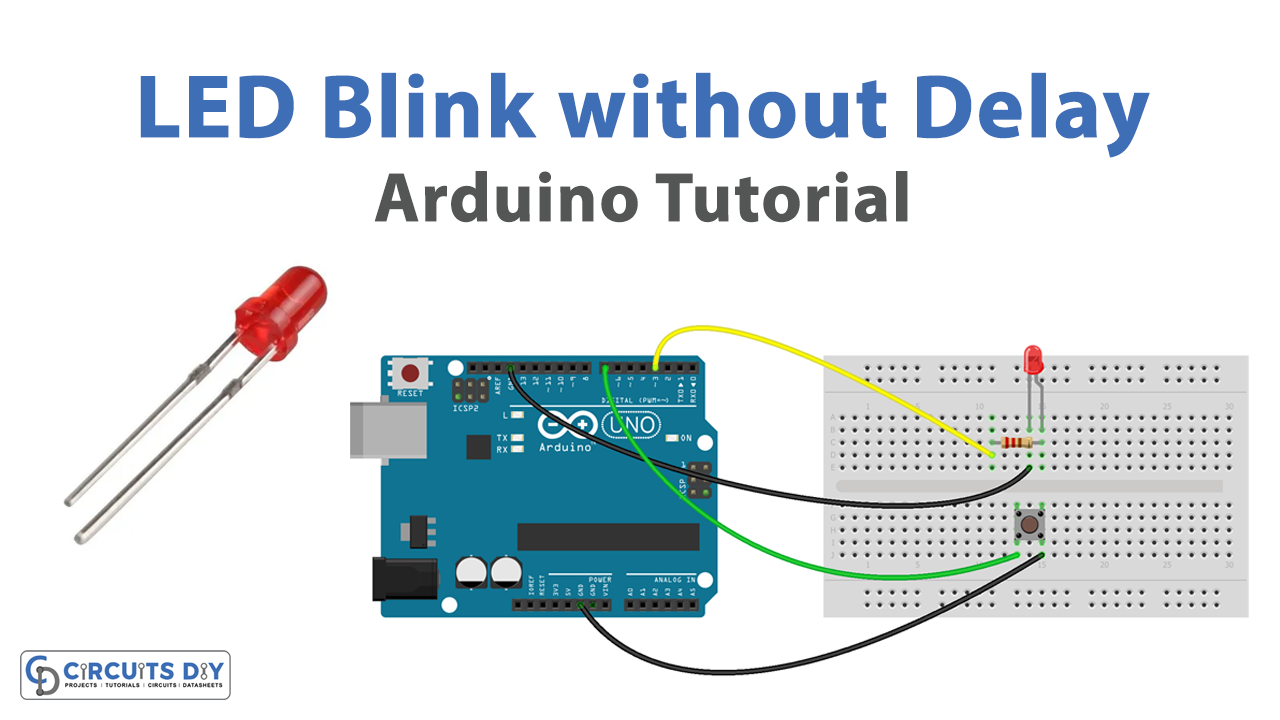
- Connect the LED to the breadboard. Connect the longer leg of the LED to a row on the breadboard, and the shorter leg to a different row.
- Connect the 220-ohm resistor to the breadboard. Connect one end of the resistor to the same row as the shorter leg of the LED, and the other end to a different row.
- Connect one end of a jumper wire to the row with the longer leg of the LED and the other end to a digital pin on the Arduino board.
- Connect the other end of the resistor to a ground pin on the Arduino board.
- Open the Arduino software on your computer.
- Create a new sketch by clicking on “File” and then “New.”
- Set the pin mode for the digital pin that the LED is connected to by adding the following line of code at the beginning of the sketch:
pinMode(pinNumber, OUTPUT);- Replace “pinNumber” with the actual number of the digital pin that the LED is connected to.
- Declare a variable to store the current state of the LED at the beginning of the sketch. This can be done with a line of code like this:
int ledState = LOW;- In the loop function, add the following lines of code to turn the LED on and off:
digitalWrite(pinNumber, ledState);ledState = !ledState;- Replace “pinNumber” with the actual number of the digital pin that the LED is connected to.
- Upload the sketch to the Arduino board by clicking the “Upload” button in the Arduino software.
Schematic
Make connections according to the circuit diagram given below.
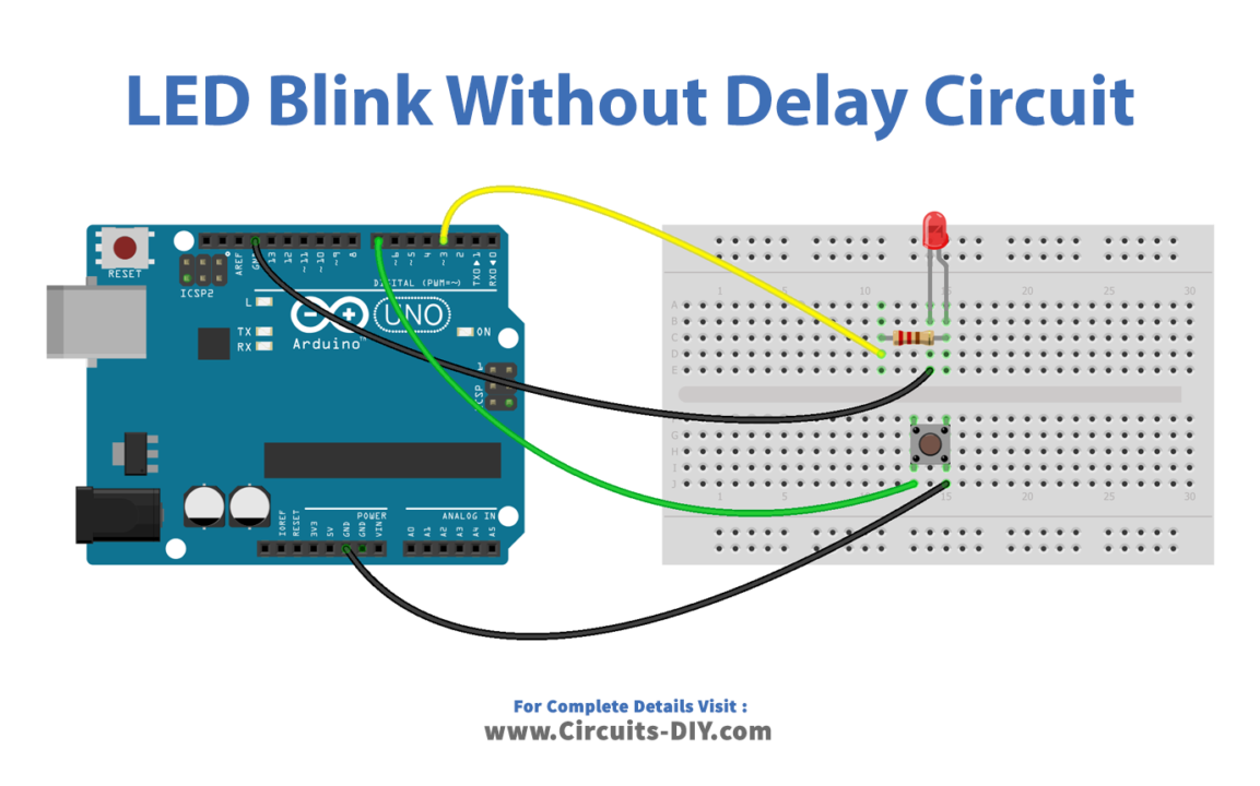
Wiring / Connections
| Arduino | LED | Button |
|---|---|---|
| 5V | with resistor D3 | One end to D7 |
| GND | GND | Other to GND |
Installing Arduino IDE
First, you need to install Arduino IDE Software from its official website Arduino. Here is a simple step-by-step guide on “How to install Arduino IDE“.
Code
Now copy the following code and upload it to Arduino IDE Software.
Arduino Code – With Delay
const int LED_PIN = 3;     // the number of the LED pin
const int BUTTON_PIN = 7;  // the number of the button pin

const long BLINK_INTERVAL = 1000;   // interval at which to blink LED (milliseconds)

// Variables will change:
int ledState = LOW;   // ledState used to set the LED

int previousButtonState = LOW; // will store last time button was updated

void setup() {
  Serial.begin(9600);

  // set the digital pin as output:
  pinMode(LED_PIN, OUTPUT);

  // set the digital pin as an input:
  pinMode(BUTTON_PIN, INPUT);
}

void loop() {
  // if the LED is off turn it on and vice-versa:
  ledState = (ledState == LOW) ? HIGH : LOW;

  // set the LED with the ledState of the variable:
  digitalWrite(LED_PIN, ledState);

  delay(BLINK_INTERVAL); // If button is pressed during this time, Arduino CANNOT detect

  int currentButtonState = digitalRead(BUTTON_PIN);

  if(currentButtonState != previousButtonState) {
    // print out the state of the button:
    Serial.println(currentButtonState);

    // save the last state of button
    previousButtonState = currentButtonState;
  }
}
Arduino Code – Without Delay
const int LED_PIN = 3;     // the number of the LED pin
const int BUTTON_PIN = 7;  // the number of the button pin

const long BLINK_INTERVAL = 1000;   // interval at which to blink LED (milliseconds)

// Variables will change:
int ledState = LOW;   // ledState used to set the LED

int previousButtonState = LOW; // will store last time button was updated

unsigned long previousMillis = 0;   // will store last time LED was updated

void setup() {
  Serial.begin(9600);

  // set the digital pin as output:
  pinMode(LED_PIN, OUTPUT);

  // set the digital pin as an input:
  pinMode(BUTTON_PIN, INPUT);
}

void loop() {
  // check to see if it's time to blink the LED; that is, if the difference
  // between the current time and last time you blinked the LED is bigger than
  // the interval at which you want to blink the LED.
  unsigned long currentMillis = millis();

  if (currentMillis - previousMillis >= BLINK_INTERVAL) {
    // if the LED is off turn it on and vice-versa:
    ledState = (ledState == LOW) ? HIGH : LOW;

    // set the LED with the ledState of the variable:
    digitalWrite(LED_PIN, ledState);

    // save the last time you blinked the LED
    previousMillis = currentMillis;
  }
// check button state's change
  int currentButtonState = digitalRead(BUTTON_PIN);

  if(currentButtonState != previousButtonState) {
    // print out the state of the button:
    Serial.println(currentButtonState);

    // save the last state of button
    previousButtonState = currentButtonState;
  }

}
Working Explanation
The code starts by setting the pin mode for the digital pin that the LED is connected to. This is done with the pinMode function, which takes two arguments: the pin number and the mode (either INPUT or OUTPUT). In this case, the pin mode is set to OUTPUT because the LED will be connected to an output pin on the Arduino board.
Next, a variable is declared to store the current state of the LED. This variable is initially set to LOW. After this, the code enters a loop that will run indefinitely. Inside the loop, the code uses the digitalWrite function to set the pin to the current value of the ledState variable. This will either turn the LED on (if the ledState variable is HIGH) or off (if the ledState variable is LOW).
After this, The code then uses the ‘!‘ operator to toggle the value of the ledState variable between HIGH and LOW. This is done with the following line of code:
ledState = !ledState;The loop then repeats, starting from the digitalWrite function. This results in the LED turning on and off continuously, without pausing in between.
Applications
- Real-time monitoring
- Timing applications
- Communication
- Interactive displays
Conclusion
We hope you have found this LED Blink without Delay Circuit very useful. If you feel any difficulty in making it feel free to ask anything in the comment section.