Introduction
An HC-SR04 ultrasonic sensor-controlled LED on an Arduino UNO is a circuit that uses an ultrasonic sensor to detect the presence of an object and control an LED based on the distance to the object. The ultrasonic sensor sends out a pulse of sound and measures the time it takes for the pulse to bounce back after hitting an object.
Based on the speed of sound and the measured time, the distance to the object can be calculated. The Arduino can then use this distance to control the state of an LED, such as turning it on or off or adjusting its brightness. The LED can be used to indicate the presence or absence of an object or to provide visual feedback based on the distance to the object.
Hardware Components
You will require the following hardware for Interfacing Ultrasonic Sensor with Arduino.
| S.no | Component | Value | Qty |
|---|---|---|---|
| 1. | Arduino UNO | – | 1 |
| 2. | USB Cable Type A to B | – | 1 |
| 3. | Ultrasonic Sensor | – | 1 |
| 4. | 9V Power Adapter for Arduino | – | 1 |
| 5. | LED | – | 1 |
| 6. | Resistor | 220Ω | 1 |
| 7. | Breadboard | – | 1 |
| 8. | Jumper Wires | – | 1 |
Ultrasonic Sensor with Arduino
- Connect the ultrasonic sensor to the Arduino according to the following:
- VCC to 5V
- GND to GND
- TRIG to a digital output pin (e.g. D9)
- ECHO to a digital input pin (e.g. D8)
- Connect the LED to the Arduino according as follows:
- Anode (longer leg) to a digital output pin (e.g. D7)
- Cathode (shorter leg) to GND
- Open the Arduino Integrated Development Environment (IDE) and create a new sketch.
- Declare the pin numbers for the TRIG, ECHO, and LED pins as constants at the top of the sketch. For example:
const int trigPin = 9;
const int echoPin = 8;
const int ledPin = 7;- In the setup function, set the pin modes for the TRIG, ECHO, and LED pins. For example:
pinMode(trigPin, OUTPUT);
pinMode(echoPin, INPUT);
pinMode(ledPin, OUTPUT);- In the loop function, send a pulse to the TRIG pin to initiate the ultrasonic measurement. This can be done using the digitalWrite and delayMicroseconds functions. For example:
digitalWrite(trigPin, HIGH);
delayMicroseconds(10);
digitalWrite(trigPin, LOW);- Measure the time it takes for the pulse to travel to an object and back by measuring the duration of the pulse on the ECHO pin. This can be done using the pulseIn function. For example:
long duration = pulseIn(echoPin, HIGH);- Calculate the distance to the object using the speed of sound and the measured duration. The distance can be calculated as follows:
int distance = duration * 0.034 / 2;- Check if the distance is within a certain range, and if it is, turn the LED on using the digitalWrite function. For example:
if (distance < 10) {
digitalWrite(ledPin, HIGH);
} else {
digitalWrite(ledPin, LOW);
}- Add a delay between measurements to give the sensor time to stabilize. This can be done using the delay function. For example:
delay(100);- Upload the sketch to the Arduino and test the circuit. The LED should turn on when an object is within range of the ultrasonic sensor.
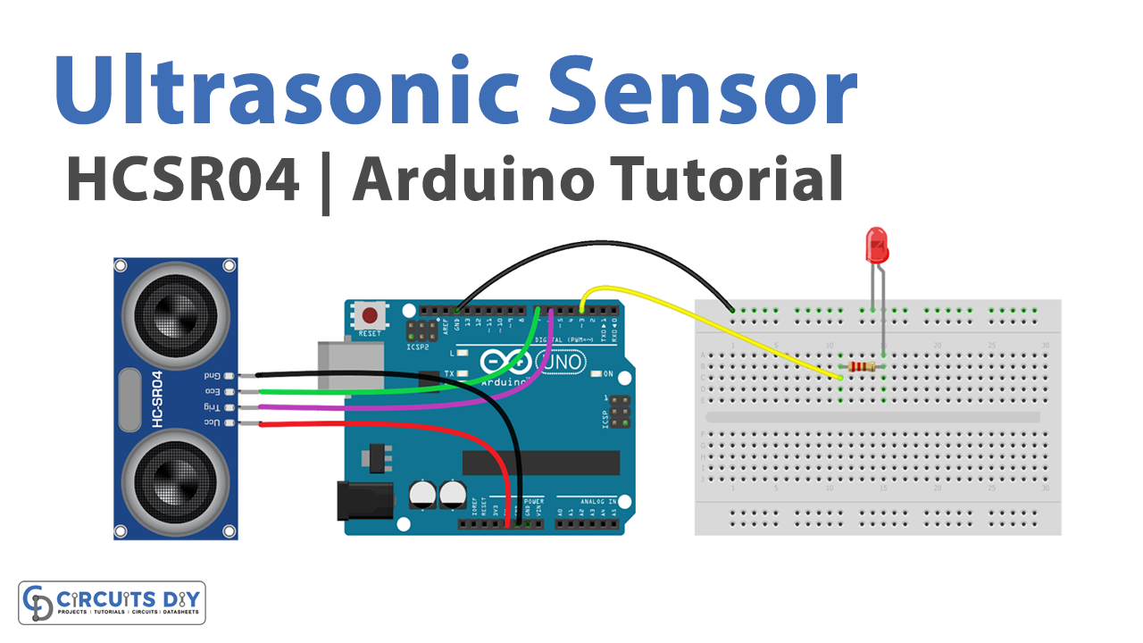
Schematic
Make connections according to the circuit diagram given below.

Wiring / Connections
| Arduino | HCSR04 |
|---|---|
| 5V | VCC |
| GND | GND |
| D6 | Trigger |
| D7 | Echo |
Installing Arduino IDE
First, you need to install Arduino IDE Software from its official website Arduino. Here is a simple step-by-step guide on “How to install Arduino IDE“.
Code
Now copy the following code and upload it to Arduino IDE Software.
const int TRIG_PIN = 6; // Arduino pin connected to Ultrasonic Sensor's TRIG pin
const int ECHO_PIN = 7; // Arduino pin connected to Ultrasonic Sensor's ECHO pin
const int LED_PIN  = 3; // Arduino pin connected to LED's pin
const int DISTANCE_THRESHOLD = 50; // centimeters

// variables will change:
float duration_us, distance_cm;

void setup() {
  Serial.begin (9600);       // initialize serial port
  pinMode(TRIG_PIN, OUTPUT); // set arduino pin to output mode
  pinMode(ECHO_PIN, INPUT);  // set arduino pin to input mode
  pinMode(LED_PIN, OUTPUT);  // set arduino pin to output mode
}

void loop() {
  // generate 10-microsecond pulse to TRIG pin
  digitalWrite(TRIG_PIN, HIGH);
  delayMicroseconds(10);
  digitalWrite(TRIG_PIN, LOW);

  // measure duration of pulse from ECHO pin
  duration_us = pulseIn(ECHO_PIN, HIGH);
  // calculate the distance
  distance_cm = 0.017 * duration_us;

  if(distance_cm < DISTANCE_THRESHOLD)
    digitalWrite(LED_PIN, HIGH); // turn on LED
  else
    digitalWrite(LED_PIN, LOW);  // turn off LED

  // print the value to Serial Monitor
  Serial.print("distance: ");
  Serial.print(distance_cm);
  Serial.println(" cm");

  delay(500);
}
Working Explanation
The working of an HC-SR04 ultrasonic sensor-controlled LED on an Arduino UNO microcontroller involves using the ultrasonic sensor to measure the distance to an object and using this measurement to control the state of an LED. In the setup function, the code sets the pin modes for the TRIG, ECHO, and LED pins. This tells the Arduino which functions the pins will be used for, such as input or output.
In the void loop function, the code sends a pulse to the TRIG pin to initiate the ultrasonic measurement. This is done using the digitalWrite and delayMicroseconds functions. The digitalWrite the function sets the state of the TRIG pin to HIGH, which sends a pulse to the sensor, and the delayMicroseconds the function adds a delay to allow the pulse to be sent.
The code then measures the time it takes for the pulse to travel to an object and back by measuring the duration of the pulse on the ECHO pin. This is done using the pulseIn function, which waits for the ECHO pin to go HIGH and measures the time it takes for the pin to go LOW. The code then checks if the distance is within a certain range, and if it is, the code turns the LED on or off, or adjusts its brightness, using the digitalWrite function.
Applications
- Distance sensing
- Obstacle avoidance
- Proximity sensing
- Presence detection
- Distance measurement
- Rangefinding
Conclusion
We hope you have found this Ultrasonic Sensor Circuit very useful. If you feel any difficulty in making it feel free to ask anything in the comment section.