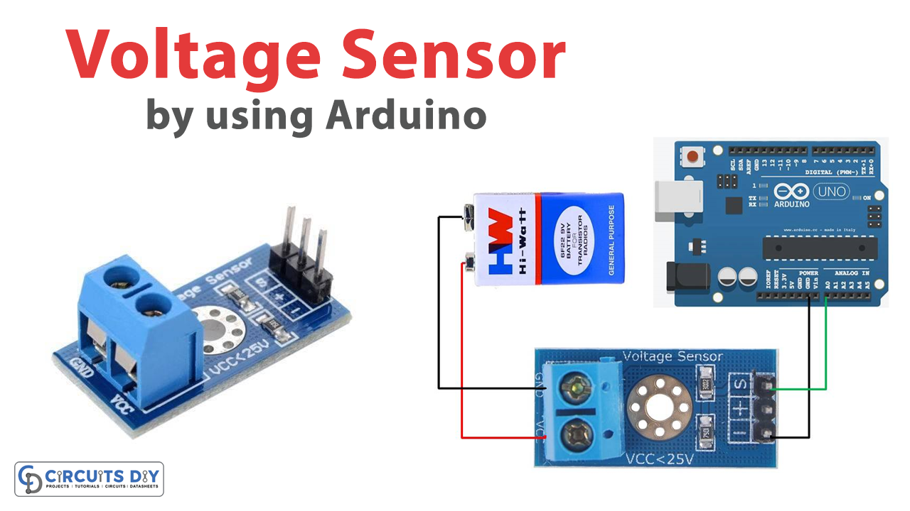
In this tutorial, we will interface “Voltage Sensor Module with Arduino”. Voltage sensors are used to estimate and monitor the quantity of voltage in a device or system.
Brief Overview of Voltage Sensor
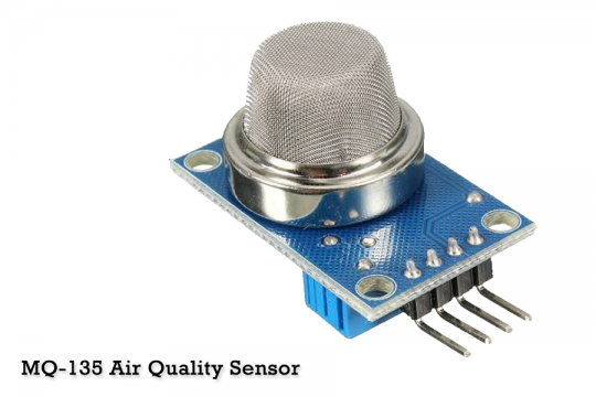
The Voltage Sensor Module is an accessible and extremely useful module that employs a potential divider to lower any input voltage. This enables us to monitor voltages greater than the microcontroller’s Analog input pin is capable of sensing. For example, a 0V To 5V Analog input range allows you to detect voltages up to 25V. This module also contains handy screw terminals for quick and secure wire connections.
Working Principle
The voltage sensor module operates according to the voltage divider technique. As you know, a voltage divider is a circuit comprised of two series-connected resistors. The circuit is fed with an input voltage. The applied voltage is subsequently transmitted between the two resistances, and division occurs in direct proportion to the resistances. The output analog voltage of the second resistor is measured.
Features and Specifications
- Input Voltage: 0 to 25V
- Voltage Detection Range: 0.02445 to 25
- Analog Voltage Resolution: 0.00489V
- Dimensions: 4 × 3 × 2 cm
- There are no external components required.
- It works well with microcontrollers.
- Small, inexpensive, and widely accessible
Pinout
| Pin Name | Description |
|---|---|
| VCC | The positive terminal of the external voltage source range from 0 to 25V |
| GND | The negative terminal of the External voltage source |
| S | The Analog pin needs to be connected to the Analog pin of the microcontroller |
| + | Not Connected |
| – | Ground Pin needs to be connected to the GND of the microcontroller |
Hardware Required
| S.no | Components | Value / Model | Qty |
|---|---|---|---|
| 1 | Arduino UNO | – | 1 |
| 2 | USB Cable Type A to B | – | 1 |
| 3 | Voltage Sensor Module | – | 1 |
| 4 | Jumper Wires | – | – |
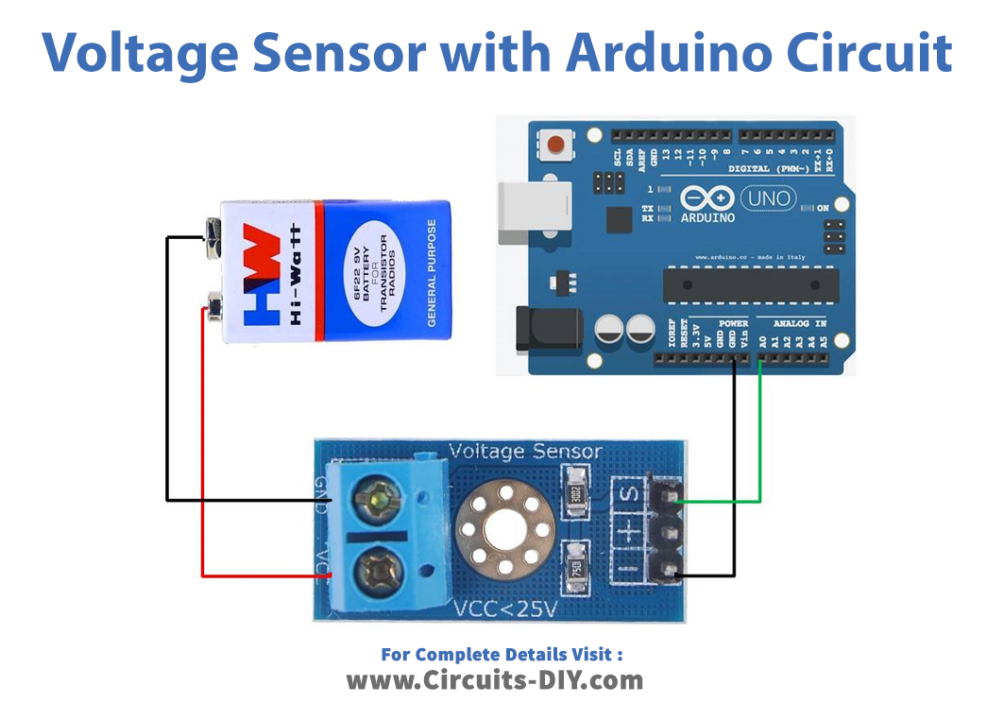
Circuit Diagram
Connection Table
| Arduino UNO | Voltage Sensor Module |
|---|---|
| GND | GND |
| A0 | S |
Arduino Code
int offset =20;// set the correction offset value
void setup() {
  // Robojax.com voltage sensor
  Serial.begin(9600);
}

void loop() {
  int volt = analogRead(A0);// read the input
  double voltage = map(volt,0,1023, 0, 2500) + offset;// map 0-1023 to 0-2500 and add correction offset

  voltage /=100;// divide by 100 to get the decimal values
  Serial.print("Voltage: ");
  Serial.print(voltage);//print the voltge
  Serial.println("V");

delay(500);
}
Working Explanation
It’s simple to connect a voltage sensor to an Arduino. Connect the voltage sensor’s screw terminals to the VCC and GND of the voltage source for which voltage is being measured. Complete the connections of the circuit according to the given diagram. Upload the code on the Arduino and check the measurements on the Serial monitor to test the module.
Code Explanation
- For interface with the Arduino microcontrollers, the voltage sensor module somehow doesn’t need an Arduino library. As a correction value for the input analog signal, a voltage offset of 20 is employed.
- In void setup, the setup block in initializes the serial monitor with a usual baud rate of 9600 bits every second. It is required to display the analog voltage signal values.
- An integer variable named “volt” is initialized within the void loop. The built-in analogRead() function is used to read and save the analog value. The map function, which converts one set of values into another set of values, is the next set of instructions. There are five parameters. The variable “volt,” whose values are to be mapped, is the first one. Because the Arduino has a 10-bit internal analog to digital converter and mapped the values in the range 0 to 2500, the values would fall between 0 and 1023. The result is saved in the “voltage” after mapping and adding the offset, which is then divided by 100 to obtain the decimal point. These are then shown on the Serial monitor, and a 500-millisecond pause occurs before reading the subsequent result. The values will be read more quickly the shorter the wait.
Application and Uses
- Voltage Monitoring
- Detection of power failure
- Temperature control
- Safety switching, etc