Introduction
We all know that computers, calculators, or any intelligent machine have registers or memory to store the data. Usually, the data required to keep have two types; permanent and temporary. To store temporary data, these machines use shift registers. A shift register is a sequential logic device that stores and transfers binary data. Shift registers are essentially bidirectional circuits that shift every bit of data in their input to their output on each clock pulse. 74HC595 belongs to one of those shift registers. So we have decided that in this tutorial, we will interface “74HC595 Shift Register with Arduino UNO”.
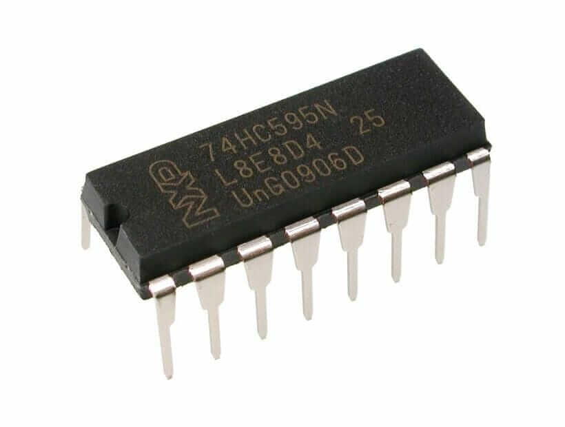
74HC595 Shift Register
The 74HCT595 is an 8-stage shift register with a 3-state output and a storage register. The clocks in the registers are separate.
Features
- 8-bit serial input
- 8-bit serial or parallel output
- Storage register with 3-state outputs
- Shift register with direct clear
- 100 MHz (typical) shift out frequency
- ESD protection:
- HBM JESD22-A114F exceeds 2000 V
- MM JESD22-A115-A exceeds 200 V
- Multiple package options
- Specified from 40 C to +85 C and from 40 C to +125 C
Pinouts
| Pin Number | Name | Description |
| 1-7 | Q1-Q7 | Parallel data output pins B-H/2-7 |
| 8 | GND | Ground |
| 9 | QH | Serial data output pin |
| 10 | CLR | Reset (active LOW) |
| 11 | SRCLK/SHCP | Storage register clock pin, SPI clock |
| 12 | RCLK/STCP | Shift register clock input, latch pin |
| 13 | OE | Output enable, active LOW |
| 14 | SER/DS | Serial data input, SPI data |
| 15 | QA | Parallel data output pin A/1 |
| 16 | VCC | positive voltage supply |
How 74HC595 Shift Register Works?
The 74HC595 is a shift register that uses the Serial IN Parallel OUT protocol to operate. It accepts serial data from the microcontroller before sending it out through parallel pins. Using a single chip, we may expand our output pins by eight. More than one shift register can be connected in parallel.
Hardware Required
| S.no | Component | Value | Qty |
|---|---|---|---|
| 1. | Arduino | UNO | 1 |
| 2. | USB Cable Type A to B | – | 1 |
| 3. | Jumper Wires | – | – |
| 4. | Shift Register | 74HC595C595 | 1 |
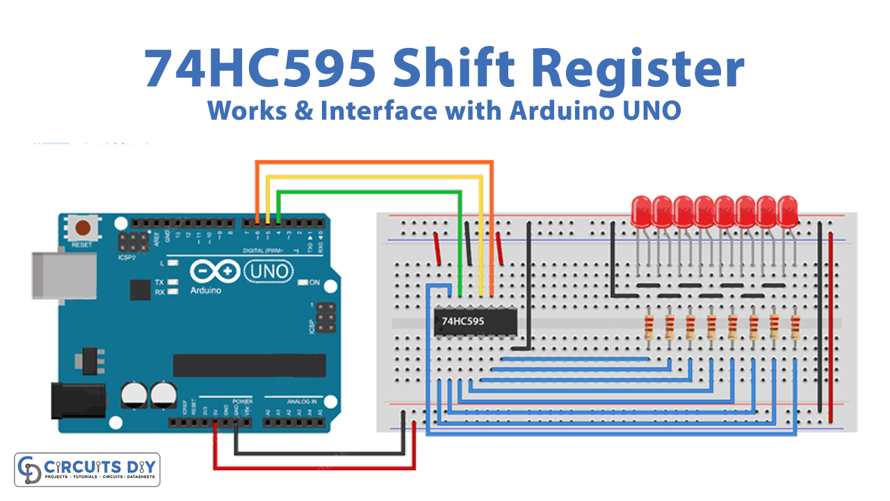
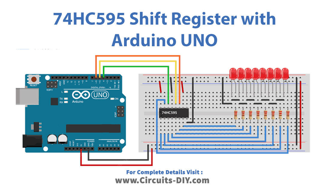
Circuit Diagram
Arduino Code
int latchPin = 5;	// Latch pin of 74HC595 is connected to Digital pin 5
int clockPin = 6;	// Clock pin of 74HC595 is connected to Digital pin 6
int dataPin = 4;	// Data pin of 74HC595 is connected to Digital pin 4

byte leds = 0;		// Variable to hold the pattern of which LEDs are currently turned on or off

/*
 * setup() - this function runs once when you turn your Arduino on
 * We initialize the serial connection with the computer
 */
void setup()
{
  // Set all the pins of 74HC595 as OUTPUT
  pinMode(latchPin, OUTPUT);
  pinMode(dataPin, OUTPUT);
  pinMode(clockPin, OUTPUT);
}

/*
 * loop() - this function runs over and over again
 */
void loop()
{
  leds = 0;	// Initially turns all the LEDs off, by giving the variable 'leds' the value 0
  updateShiftRegister();
  delay(500);
  for (int i = 0; i < 8; i++)	// Turn all the LEDs ON one by one.
  {
    bitSet(leds, i);		// Set the bit that controls that LED in the variable 'leds'
    updateShiftRegister();
    delay(500);
  }
}

/*
 * updateShiftRegister() - This function sets the latchPin to low, then calls the Arduino function 'shiftOut' to shift out contents of variable 'leds' in the shift register before putting the 'latchPin' high again.
 */
void updateShiftRegister()
{
   digitalWrite(latchPin, LOW);
   shiftOut(dataPin, clockPin, LSBFIRST, leds);
   digitalWrite(latchPin, HIGH);
}
Working Explanation
Connect the 74HC595 Shift Register to Arduino. Copy and paste the code from this page into your Arduino IDE. Then, on the board, upload the code. You will now be able to see the light shifting in LEDs.
Please ensure the LEDs are wired in the proper order when placing them, with QA linked to the first LED and QH connected to the last, else our code will not light up the LEDs in the correct order!\
Code Explanation
- The first step is to specify the three control pins of the 74HC595, namely the latch, clock, and data pins, which will be connected to the Arduino’s digital pins 5, 6, and 4 correspondingly. Then, we have defined the variable ‘leds’ . This will be used to keep track of which LEDs are ON or OFF at any one time. The data type byte represents numbers that are eight bits long. Because each bit can be turned on or off, this is ideal for keeping record of which of our eight LEDs is active.
- In the void setup, we declared those defined pins as the output.
- In the void loop, By setting the variable leds to 0, we first turn off all the LEDs. It then runs updateShiftRegister(), a custom function that sends the ‘leds’ pattern to the shift register, turning off all of the LEDs. The code comes to a halt for a half second before counting from 0 to 7 using the for loop and the variable i. It calls the function bitSet() each time to set the bit that regulates a specific LED in the variable ‘leds.’ It then calls updateShiftRegister() to modify the state of LEDs based on the value of the variable ‘leds.’After that, there is a half-second pause before I is incremented and the next LED is turned on. The first two arguments of the shiftOut() function are the pins to utilise for Data and Clock, respectively. The third argument determines where you want to start with the data. We’ll start with the rightmost bit, which is also known as the LSB.
Application and Uses
- Shift registers are used to store temporary data.
- Data transport and manipulation are also done with shift registers.
- Counters, computers, calculators can utilize the shift register.