Introduction
This article is about interfacing a PN532 NFC RFID Module with Arduino. Interfacing the PN532 NFC RFID module with an Arduino board is a great way to add a new dimension of functionality to your projects. The PN532 module can read and write to RFID tags and cards, making it a versatile tool for applications such as access control systems, inventory management, and even contactless payments.
In this article, we will cover the steps needed to connect the two devices and some of the necessary code. By the end of this tutorial, you will have a basic understanding of how the PN532 module works, and you’ll be able to write your code to communicate with it using an Arduino board. So, let’s dive into the world of NFC and RFID technology with the PN532 NFC RFID module.
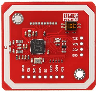
What is PN532 NFC RFID Module?
The PN532 is a simple Arduino-based NFC RFID module. Because it has a unique capability, this module stands apart from the other RFIC modules and devices in several respects. The PN532 functions provide communication functions carried out with an NFC chip. The module serves several purposes, including transmitting data, reading RFIC cards, and working as an RFID reader. The device is effective at a close range of 5-7 centimeters.
Hardware Components
You will require the following hardware for Interfacing PN532 NFC RFID Module with Arduino.
| S.no | Component | Value | Qty |
|---|---|---|---|
| 1. | Arduino UNO | – | 1 |
| 2. | NFC Module | PN532 | 1 |
| 3. | Breadboard | – | 1 |
| 4. | Jumper Wires | – | 1 |
PN532 NFC RFID Module with Arduino
Now that you have got an idea about the module and its working, it’s time to interface the circuit. Hence, for that, you need to follow the given steps:
Schematic
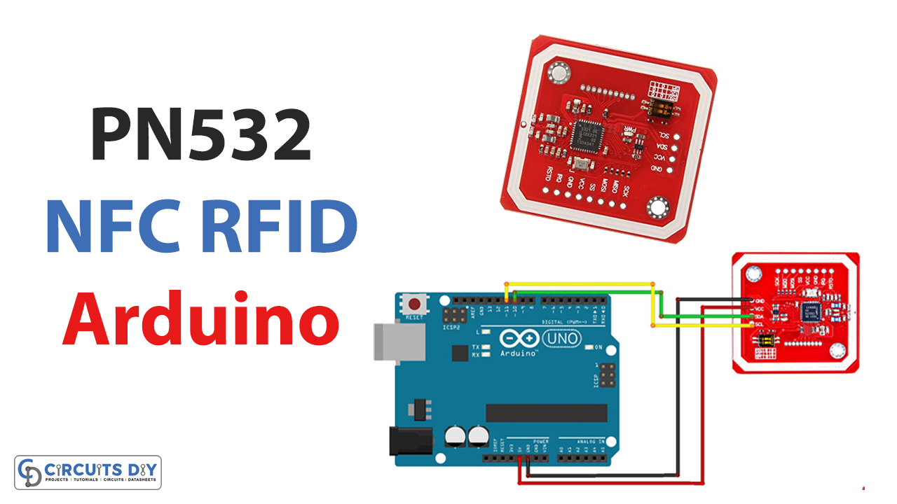
Make connections according to the circuit diagram given below.
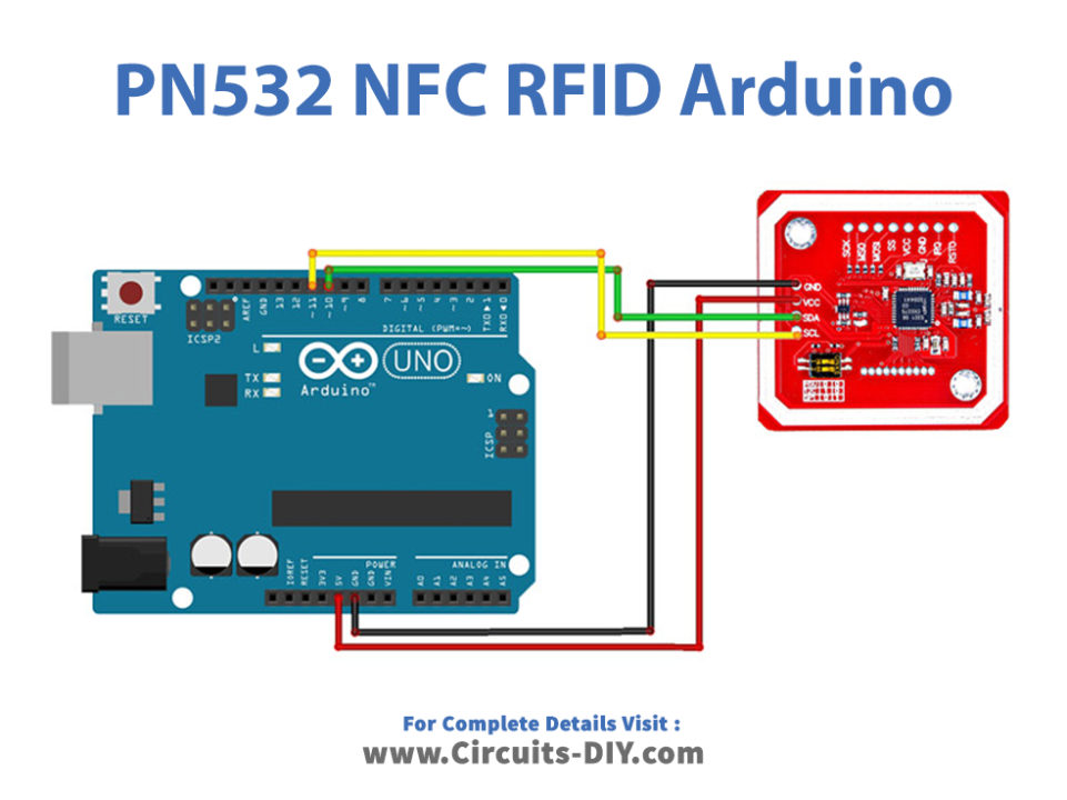
Wiring / Connections
| Arduino | PN532 NFC Module |
|---|---|
| 5V | VCC |
| GND | GND |
| D10 | SDA |
| D11 | SCL |
Installing Arduino IDE
First, you need to install Arduino IDE Software from its official website Arduino. Here is a simple step-by-step guide on “How to install Arduino IDE“.
Installing Libraries
Before you start uploading a code, download and unzip the following libraries at /Progam Files(x86)/Arduino/Libraries (default), in order to use the sensor with the Arduino board. Here is a simple step-by-step guide on “How to Add Libraries in Arduino IDE“.
Code
Now copy the following code and upload it to Arduino IDE Software.
#include <SoftwareSerial.h>
#include <PN532_SWHSU.h>
#include <PN532.h>

SoftwareSerial SWSerial( 10, 11 ); // RX, TX

PN532_SWHSU pn532swhsu( SWSerial );

PN532 nfc( pn532swhsu );


void setup(void) {

  Serial.begin(115200);

  Serial.println("Hello Maker!");

  nfc.begin();

  uint32_t versiondata = nfc.getFirmwareVersion();

  if (! versiondata) {

    Serial.print("Didn't Find PN53x Module");

    while (1); // Halt

  }

  // Got valid data, print it out!

  Serial.print("Found chip PN5"); Serial.println((versiondata>>24) & 0xFF, HEX);

  Serial.print("Firmware ver. "); Serial.print((versiondata>>16) & 0xFF, DEC);

  Serial.print('.'); Serial.println((versiondata>>8) & 0xFF, DEC);

  // Configure board to read RFID tags

  nfc.SAMConfig();

  Serial.println("Waiting for an ISO14443A Card ...");

}

void loop(void) {

  boolean success;

  uint8_t uid[] = { 0, 0, 0, 0, 0, 0, 0 };  // Buffer to store the returned UID

  uint8_t uidLength;                       // Length of the UID (4 or 7 bytes depending on ISO14443A card type)

success = nfc.readPassiveTargetID(PN532_MIFARE_ISO14443A, &uid[0], &uidLength);

  if (success) {

    Serial.println("Found A Card!");

    Serial.print("UID Length: ");Serial.print(uidLength, DEC);Serial.println(" bytes");

    Serial.print("UID Value: ");

    for (uint8_t i=0; i < uidLength; i++)

    {

      Serial.print(" 0x");Serial.print(uid[i], HEX);

    }

    Serial.println("");

    // 2 second halt

    delay(2000);

  }

  else

  {

    // PN532 probably timed out waiting for a card

    Serial.println("Timed out! Waiting for a card...");

  }
}
Let’s Test It
It’s time to test the circuit once you upload the code. The Arduino can start working as soon as it receives power. The code will cause the Arduino to read from the sensor accordingly.
Working Explanation
It is the coding that allows the circuit to function. So here’s the code explanation:
- The code starts by including several libraries, including the SoftwareSerial library, which allows for serial communication on the Arduino board; the PN532_SWHSU library, which is specific to the PN532 module and provides functions for interacting with it; and the PN532 library, which contains general functions for communicating with the PN532.
- In the void setup() function, the code initializes serial communication at a baud rate of 115200, prints “Hello Maker!” to the serial monitor, initializes the PN532 module, and checks if it is properly connected. If it is, it prints out the chip type and firmware version. Then it configures the board to read RFID tags by calling the nfc.SAMConfig() function.
- In the void loop() function, the code attempts to read a passive target ID using the nfc.readPassiveTargetID() function. If a card is found, it prints the length and value of the UID (unique identifier) of the card to the serial monitor. If a card is not found, it prints “Timed out! Waiting for a card…” to the serial monitor. The code then waits for 2 seconds before trying to read another card.
Applications
- Security systems
- Car keys, door keys
- Mobile phones, etc
Conclusion.
We hope you have found this Interfacing PN532 NFC RFID Module with Arduino Circuit very useful. If you feel any difficulty in making it feel free to ask anything in the comment section.