Introduction
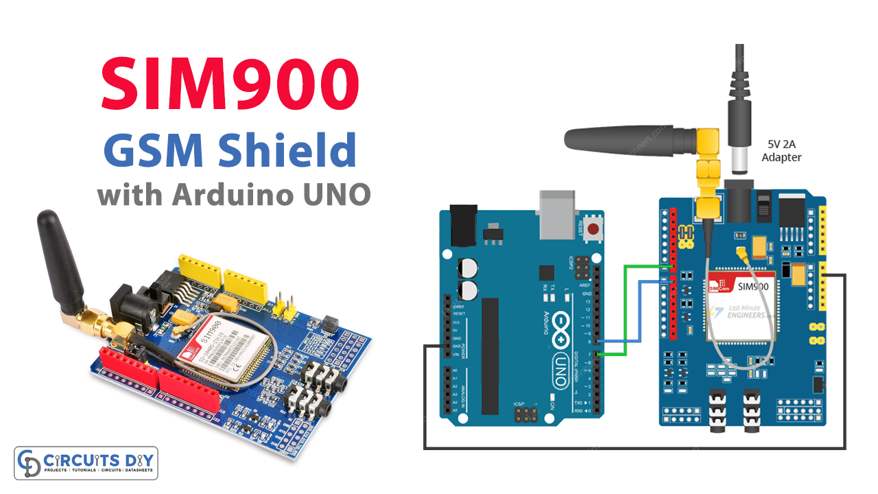
If you aspire to send any message from your electronic device, if you require to get updates on any of your projects, or if you want to deliver or receive a call from that project, then the SIM900 shield is a great option for you to use. Moreover, the module can further help you to send or receive the GPRS data. However, this must have to be considered that the module only accepts the full-size SIM card. So, in this tutorial, we are going to interface ” SIM900 GSM Shield with Arduino UNO”.
An Overview of SIM900 Sheild
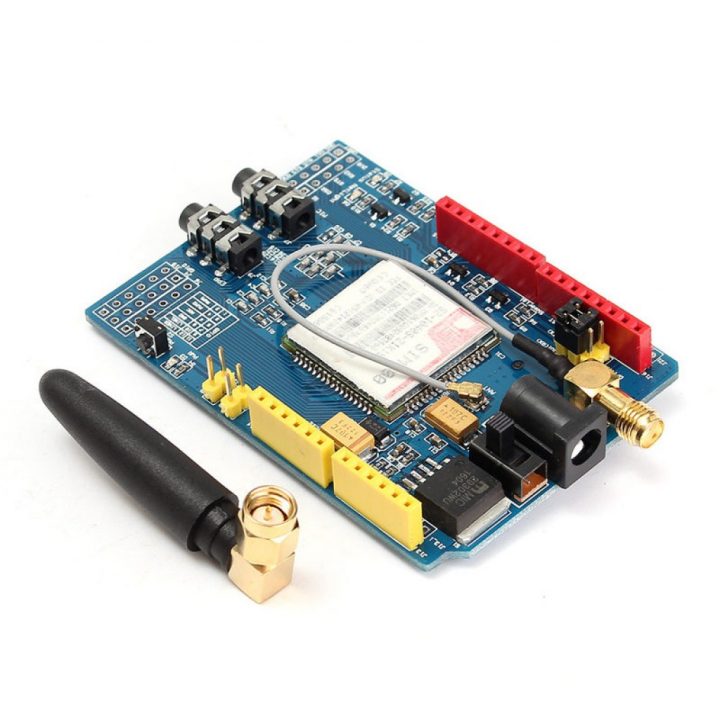
The SIM900 shield has a chip that has some unique features. One can connect to any required global network by any 2G SIm through this module. Also, the module comprises three LEDs that display the power and the connectivity status The module has an operating voltage range of 3.4V to 4.4V. Furthermore, the module shield holds high accuracy, high current, and low voltage dropout regulator. And, it can easily handle the current up to 3A.
Hardware Required
| S.no | Component | Value | Qty |
|---|---|---|---|
| 1. | Arduino UNO | – | 1 |
| 2. | USB Cable Type A to B | – | 1 |
| 3. | Jumper Wires | – | – |
| 4. | GSM Shield | SIM900 | 1 |
Circuit Diagram

Arduino Code
Testing AT Commands
#include <SoftwareSerial.h>

//Create software serial object to communicate with SIM900
SoftwareSerial mySerial(7, 8); //SIM900 Tx & Rx is connected to Arduino #7 & #8

void setup()
{
  //Begin serial communication with Arduino and Arduino IDE (Serial Monitor)
  Serial.begin(9600);

  //Begin serial communication with Arduino and SIM900
  mySerial.begin(9600);

  Serial.println("Initializing...");
  delay(1000);

  mySerial.println("AT"); //Handshaking with SIM900
  updateSerial();
  mySerial.println("AT+CSQ"); //Signal quality test, value range is 0-31 , 31 is the best
  updateSerial();
  mySerial.println("AT+CCID"); //Read SIM information to confirm whether the SIM is plugged
  updateSerial();
  mySerial.println("AT+CREG?"); //Check whether it has registered in the network
  updateSerial();
}

void loop()
{
  updateSerial();
}

void updateSerial()
{
  delay(500);
  while (Serial.available())
  {
    mySerial.write(Serial.read());//Forward what Serial received to Software Serial Port
  }
  while(mySerial.available())
  {
    Serial.write(mySerial.read());//Forward what Software Serial received to Serial Port
  }
}
Arduino Code – Sending SMS
#include <SoftwareSerial.h>

//Create software serial object to communicate with SIM900
SoftwareSerial mySerial(7, 8); //SIM900 Tx & Rx is connected to Arduino #7 & #8

void setup()
{
  //Begin serial communication with Arduino and Arduino IDE (Serial Monitor)
  Serial.begin(9600);

  //Begin serial communication with Arduino and SIM900
  mySerial.begin(9600);

  Serial.println("Initializing...");
  delay(1000);

  mySerial.println("AT"); //Handshaking with SIM900
  updateSerial();

  mySerial.println("AT+CMGF=1"); // Configuring TEXT mode
  updateSerial();
  mySerial.println("AT+CMGS=\"+ZZxxxxxxxxxx\"");//change ZZ with country code and xxxxxxxxxxx with phone number to sms
  updateSerial();
  mySerial.print("Last Minute Engineers | lastminuteengineers.com"); //text content
  updateSerial();
  mySerial.write(26);
}

void loop()
{
}

void updateSerial()
{
  delay(500);
  while (Serial.available())
  {
    mySerial.write(Serial.read());//Forward what Serial received to Software Serial Port
  }
  while(mySerial.available())
  {
    Serial.write(mySerial.read());//Forward what Software Serial received to Serial Port
  }
}
Arduino Code – Reading SMS
#include <SoftwareSerial.h>

//Create software serial object to communicate with SIM900
SoftwareSerial mySerial(7, 8); //SIM900 Tx & Rx is connected to Arduino #7 & #8

void setup()
{
  //Begin serial communication with Arduino and Arduino IDE (Serial Monitor)
  Serial.begin(9600);

  //Begin serial communication with Arduino and SIM900
  mySerial.begin(9600);

  Serial.println("Initializing...");
  delay(1000);

  mySerial.println("AT"); //Handshaking with SIM900
  updateSerial();

  mySerial.println("AT+CMGF=1"); // Configuring TEXT mode
  updateSerial();
  mySerial.println("AT+CNMI=1,2,0,0,0"); // Decides how newly arrived SMS messages should be handled
  updateSerial();
}

void loop()
{
  updateSerial();
}

void updateSerial()
{
  delay(500);
  while (Serial.available())
  {
    mySerial.write(Serial.read());//Forward what Serial received to Software Serial Port
  }
  while(mySerial.available())
  {
    Serial.write(mySerial.read());//Forward what Software Serial received to Serial Port
  }
}
Making Call
#include <SoftwareSerial.h>

//Create software serial object to communicate with SIM900
SoftwareSerial mySerial(7, 8); //SIM900 Tx & Rx is connected to Arduino #7 & #8

void setup()
{
  //Begin serial communication with Arduino and Arduino IDE (Serial Monitor)
  Serial.begin(9600);

  //Begin serial communication with Arduino and SIM900
  mySerial.begin(9600);

  Serial.println("Initializing...");
  delay(1000);

  mySerial.println("AT"); //Handshaking with SIM900
  updateSerial();

  mySerial.println("ATD+ +ZZxxxxxxxxxx;"); //  change ZZ with country code and xxxxxxxxxxx with phone number to dial
  updateSerial();
  delay(20000); // wait for 20 seconds...
  mySerial.println("ATH"); //hang up
  updateSerial();
}

void loop()
{
}

void updateSerial()
{
  delay(500);
  while (Serial.available())
  {
    mySerial.write(Serial.read());//Forward what Serial received to Software Serial Port
  }
  while(mySerial.available())
  {
    Serial.write(mySerial.read());//Forward what Software Serial received to Serial Port
  }
}
Arduino Code – Receiving Call
#include <SoftwareSerial.h>

//Create software serial object to communicate with SIM900
SoftwareSerial mySerial(7, 8); //SIM900 Tx & Rx is connected to Arduino #7 & #8

void setup()
{
  //Begin serial communication with Arduino and Arduino IDE (Serial Monitor)
  Serial.begin(9600);

  //Begin serial communication with Arduino and SIM900
  mySerial.begin(9600);

  Serial.println("Initializing...");
}

void loop()
{
  updateSerial();
}

void updateSerial()
{
  delay(500);
  while (Serial.available())
  {
    mySerial.write(Serial.read());//Forward what Serial received to Software Serial Port
  }
  while(mySerial.available())
  {
    Serial.write(mySerial.read());//Forward what Software Serial received to Serial Port
  }
}
Working Explanation
To interface SIM900 GSM Shield & Arduino connect the circuit according to the circuit diagram. Now, for the initialization of commands use AT command code and upload the code in Arduino IDE. Hence you will analyze the initialization of the commands on the serial monitor. Write the sending SMS code and upload that too to send the message. To receive the message, write the receiving message code and upload it to your Arduino. To make a call, upload the code of making the call. And, to receive the call, write the code for receiving the code. Also, you can observe the readings on the Serial Monitor.
Code Explanation
- First, include the SoftwareSerial.h library. Then Initialize the Arduino pins that are connected to the transmitter and the receiver pins.
- After that, in the void setup, Initialize the serial monitor by Serial.begin( ). Initialize the link between the module and Arduino by using mySerial.begin( ). Then, create the basic connections to communicate with the GSM module. Send different commands by using mySerial. println( ). In the bracket write some commands. For instance, use AT command to send some commands to query the module. In the same way, use AT+CSQ to test the signal quality. Similarly, to read the sim data use AT+CCID. Hence to check whether you are registered on the network, use AT+CREG?.
- In the void loop, call the function updateSerial( ) to wait for the coming input from the serial monitor and then send it to the module by the receiver pin (D2) of the module. Also, it read the transmitter pin (D3) continuously.
For SMS
FOR SENDING SMS:
- The code is essentially the same as the given code of AT command except for some snippets. There are some changes to be made in the void setup. In the void setup, write mySerial.prinln(AT+CMGF=1) to choose the format of the message. Also, write mySerial.prinln(AT+CMGS=\”+ZZxxxxxxxxx\”) to transmit the SMS to this given phone number. Then use mySerial. Print( ) to send the text message to that number.
FOR RECEIVING SMS:
- The code is identical to the given code of AT command except for some snippets. Like in the void setup, use mySerial.prinln(AT+CMGF=1) to select the message format as text. Hence use mySerial. printin(“AT+CNMI=1,2,0,0,0”) to receive the message.
For Call
FOR MAKING A CALL:
- For this code, only Create some changes in the void setup of the above code. Use mySerial.prinln(“AT”) for the handshake. Now, use mySerial.prinln(AT+CMGS=\”+ZZxxxxxxxxx\”) to make a call on this phone number given in the bracket. Use mySerial.prinln(“ATH”) to hang up the call.
FOR RECEIVING THE CALL:
- programming for taking the call is very simple. It needs no extra effort. Same as the above code, except for the setup function. The setup function, only demands initializing the serial monitor.
Application and Uses
- In robotics
- In computer peripherals
- USB dongles.
- In automobiles
- For cellular communication
Related posts:
 Ultrasonic Sensor - Arduino Tutorial
 How to Interface LM35 and LM34 Temperature Sensors with Arduino UNO
 DS3231 Real Time Clock RTC Module - Arduino Tutorial
 Send Receive SMS & Call with A6 GSM Module & Arduino
 Interfacing HC-SR501 PIR Motion Sensor with Arduino UNO
 Interfacing HC-06 Bluetooth Wireless Module with Arduino


