Introduction
We frequently heard news reports about industrial boiler and burner explosions, which do result in the terrible deaths of several people. Safety precautions must be taken, especially in locations like these with high temperatures, which is why using a flame sensor in these environments is vitally essential.
The selection of a flame detector for a fire prevention system depends on several variables, some of which may be learned from the study of the various technologies. Hence, there are many different types of flame sensors available. Here in this article, we will interface an IR flame sensor with the Arduino
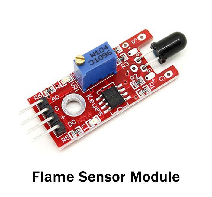
What is Flame Sensor?
Flame sensors are optoelectronic devices that detect the presence and severity of the fire and send signals to control device inputs. A flame detector is primarily used in combustion control applications, including burners, to detect the presence of flame using UV or infrared light.
Hardware Components
You will require the following hardware for Interfacing Flame Sensor with Arduino.
| S.no | Component | Value | Qty |
|---|---|---|---|
| 1. | Arduino UNO | – | 1 |
| 2. | IR Flame Sensor | – | 1 |
| 3. | Breadboard | – | 1 |
| 4. | Jumper Wires | – | 1 |
Steps in Making a Flame Sensor
To interface this Flame Sensor with Arduino, you need to have some components that are listed above in the table. Once you get them, follow the given steps:
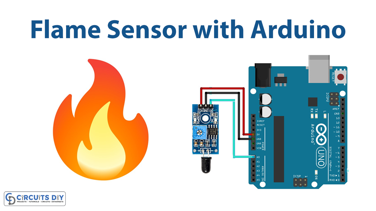
Schematic
Make connections according to the circuit diagram given below.

Wiring / Connections
| Arduino | IR Flame Sensor |
|---|---|
| 5V | VCC |
| GND | GND |
| A0 | A0 |
Installing Arduino IDE
First, you need to install Arduino IDE Software from its official website Arduino. Here is a simple step-by-step guide on “How to install Arduino IDE“.
Code
Now copy the following code and upload it to Arduino IDE Software.
// lowest and highest sensor readings:
const int sensorMin = 0;     // sensor minimum
const int sensorMax = 1024;  // sensor maximum

void setup() {
  // initialize serial communication @ 9600 baud:
  Serial.begin(9600);
}
void loop() {
  // read the sensor on analog A0:
  int sensorReading = analogRead(A0);
  // map the sensor range (four options):
  // ex: 'long int map(long int, long int, long int, long int, long int)'
  int range = map(sensorReading, sensorMin, sensorMax, 0, 3);

  // range value:
  switch (range) {
  case 0:    // A fire closer than 1.5 feet away.
    Serial.println("** Close Fire **");
    break;
  case 1:    // A fire between 1-3 feet away.
    Serial.println("** Distant Fire **");
    break;
  case 2:    // No fire detected.
    Serial.println("No Fire");
    break;
  }
  delay(1);  // delay between reads
}
Let’s Test It
It’s now time to test the circuit! After uploading the code open the serial monitor. The flame sensor must be constantly updated in to provide real-time feedback.
Working Explanation
Its important t understand the code to understand the working of the entire circuit:
- We first describe the minimum and maximum values of the sensor and name them
- In the void setup, we initialize the serial monitor to begin communication with the serial monitor
- In the void loop, The analog readings provided by the flame sensor are mapped and read using the following code. The stock flame sensor will respond as follows:
- When a flame is held within 1.5 feet of the sensor, “case 0” is initiated and the message ” ** Close Fire ** ” is sent to the serial monitor.
- When a flame is held between 1.5 and 3 feet in front of the sensor, “case 1″ is started and the message”Distant Fire” is sent to the serial monitor.
- If there is no flame in front of the sensor, “case 2” is activated, and a “No Fire” message is shown on the serial monitor
Applications
- Industrial boilers
- Combustion control
- Flame and fire detection; etc
Conclusion
We hope you have found this Flame Sensor Circuit very useful. If you feel any difficulty in making it feel free to ask anything in the comment section.