Introduction
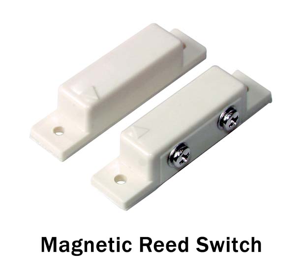
To control the flow of electricity in the circuits, the designer has come up with an idea of a Reed switch. A reed switch is an electrical switch that is regulated by applying the magnetic field. They are reliable switches having long-term integrity when interfaced with a microprocessor or microcontroller loads. Certainly, the switch is made from the ferrous reeds covered in a tiny gas tube like an envelope. This becomes magnetized, and also starts to move when the magnetic field starts to move towards the switch. So, In this tutorial, we will demonstrate that how to interface “Magnetic Reed Switch with Arduino UNO.
Benefits of Reed Switch
The reed switch has two components in it, the switch, and the magnet. Unlike mechanical switches, it doesn’t need anything physical to drive it. It is entirely driven by an invisible field around it. Also, it doesn’t require any supply voltage. Since it’s has a shield of the glass tube, that’s why it is protected from corrosion. “.
Hardware Required
| S.no | Component | Value | Qty |
|---|---|---|---|
| 1. | Arduino | UNO | 1 |
| 2. | USB Cable Type A to B | – | 1 |
| 3. | Jumper Wires | – | 1 |
| 4. | Magnetic Reed Switch | – | 1 |
| 5. | LED | – | 1 |
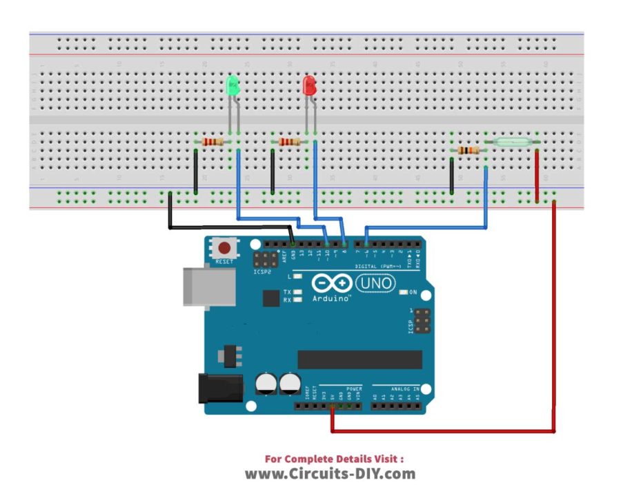
Circuit Diagram
Connection Table
| Arduino | Magnetic Reed Switch |
|---|---|
| GND | GND |
| D6 | IN1 |
| 5V | VCC |
| NO1 | |
Arduino Code
// Circuits DIY
// For Complete Details Visit -> https://circuits-diy.com

int ledOpen=8;
int ledClose=10;
int switchReed=6;

void setup(){
  pinMode(ledOpen, OUTPUT);
  pinMode(ledClose, OUTPUT);
  pinMode(switchReed, INPUT);
  Serial.begin(9600);
}

void loop(){

  if (digitalRead(switchReed)==HIGH){
    digitalWrite(ledOpen, LOW);
    digitalWrite(ledClose, HIGH);
    Serial.println("Your Door is Closed");
  }
  else {
    digitalWrite(ledOpen, HIGH);
    digitalWrite(ledClose, LOW);
    Serial.println("Your Door is Open");
  }
  delay(1);
}
Working Explanation
Build the connections according to the circuit diagram. Connect one end of this magnetic reed switch to the digital input pin of an Arduino. Here we have used pin no 6 for this purpose. Connect the other end of the reed switch to the ground. When the reed switch gets activated through an invisible magnet, Arduino reed the status of the switch. Then, the digital input pin of an Arduino changes its state. And, LEDs or any other load connected with an Arduino as output work accordingly.
Code Explanation
Upload the above-mentioned code. Define the pins through which output LEDs and input switch is connected. Define their status, whether it’s an input or output in the void setup. Here we are using pins 8 and 10 for output LEDs. While pin 6 for reed switch. Describe in the void loop that when the switch gets active which LED goes high and which LED goes low. In the same vein, describe the situation when the reed switch gets inactive. Upload the code in the Arduino for use.
Application and Uses
- For Automatic doors
- Found in an Alarm system
- To switch ON and OFF the Laptops, tablets, etc
- In automotive industry
- In modern refrigerator