Introduction
In recent years, you may have heard the terms “smart city”, “smart environment”, “smart homes”, etc. These all employ information and communication technology to improve operational efficiency. They use IoT devices like sensors, meters, etc to gather and analyze data. Then they use this data to improve infrastructure, public services, utilities, etc. Hence, these all these smart infrastructure needs IoT devices to serve their purpose. With an increasing number of IoT applications, LoRa devices are making business performances better and improving lives around the world. So, in this article, we will discuss how to interface or use LoRa RYLR998 Modules with Arduino.
Overview of LoRa RYLR998 Module
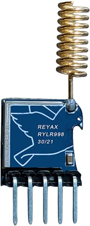
The RYLR998 transceiver module includes a long-range modem that gives ultra-long range spread spectrum communication and has excellent blocking immunity and high sensitivity. The module incorporates a Smart receiving power-saving mode. It is easy to control the module by AT commands. Moreover, the module contains a built-in antenna that makes it easier to send or receive the data.
Pinouts RYLR998
| Pin Number | Pin Name | Description |
| 1 | Vdd | Power Supply pin |
| 2 | NRST | Active low Reset Pin |
| 3 | RXD | UART Data Input |
| 4 | TXD | UART Data Output |
| 5 | GND | Ground |
LoRa RYLR998 Module with Arduino
Now, we will see how to interface the Arduino with RYLR998 LoRa Module and control the relay through that. Below are the required components, coding, circuit diagram, etc for this interfacing.
Components Required
| S.no | Component | Value | Qty |
|---|---|---|---|
| 1. | Lora | RYLR998 | 1 |
| 2. | Arduino | – | 1 |
| 3. | Resistor | 4.7K, 10K | 1, 1 |
| 4. | LED | – | 1 |
| 4. | Push-button | – | 1 |
| 5. | supply | 9V | 1 |
| 6. | Relay module | – | 1 |
| 7. | Breadboard | – | 1 |
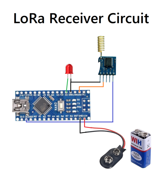
Circuit Diagram

Setting Parameter
Before connecting the LoRA module with Arduino, you have to set some parameters like Address, Band for the Lora module using AT commands.
- First Connect the Lora module with the laptop. In the Arduino IDE select the PORT Tool–>PortOpen the Serial Monitor and set the Brud rate to 115200.
- Now we can set the parameters with some basic AT commands.
- First, type AT then press enter key. We should get +OK in the serial monitor.
- Then type AT+ADDRESS to set the address to 0 for transmitter Lora.
- Then type AT+NETWORKID to set the loRa ID Network.
- Type AT+BAND to set the frequency of the wireless band.
- Use AT+PARAMETER for setting the RF wireless parameters.
Arduino Code
Transmitter Code
define LEDPin 2
define PSwitch 13

int toggleState_1 = 0// Define integer to remeber the toggle state


void setup()
{

pinMode(LEDPin, OUTPUT);
pinMode(PSwitch, OUTPUT);
}

void loop()
{

if (digitalRead (PSwitch) == HIGH){
  if toggleState_1 == 0) (
Serial.print("AT+SEND=1, 6, LEDON");
digitalWrite(LEDPin, HIGH);
toggleState_1=1;
delay(500);
}
}
Reciever Code
#define LEDPin 2
String incomingstring


void setup()
{
  Serial.begin(115200);


  pinMode(LEDPin, OUTPUT);

}

  void loop()
{

  if (serial.available())){
     incomingstring= Serial.readString();
      if (incomingstring. indexof("LEDON") >0) {
        digitalWrite(LEDPin, HIGH);
}
    else if (incomingstring. indexof("LEDOFF") >0) {
        digitalWrite(LEDPin, LOW);
}

}
}
  }
Circuit Explanation
Transmitter Side
In the transmitter circuit, we connect the TX pin of the Lora module with the RX pin of an Arduino with the help of a voltage divider. The Arduino transfers the signal at the 5V logic level but the Lora module can receive the signal at the 3.3V logic level. And therefore voltage divider is required to drop 5V to 3.3V.
Receiver Side
At the receiver Lora circuit, the TX pin of the Lora module is connected with the RX pin of an Arduino. Since Arduino has an option to receive the signal at 3.3v logic level from the LoRa module, hence doesn’t require any divider circuit.
Applications
- Smart city
- Smart agriculture
- Industrial monitoring
- Home security
- Smart homes, etc