Introduction
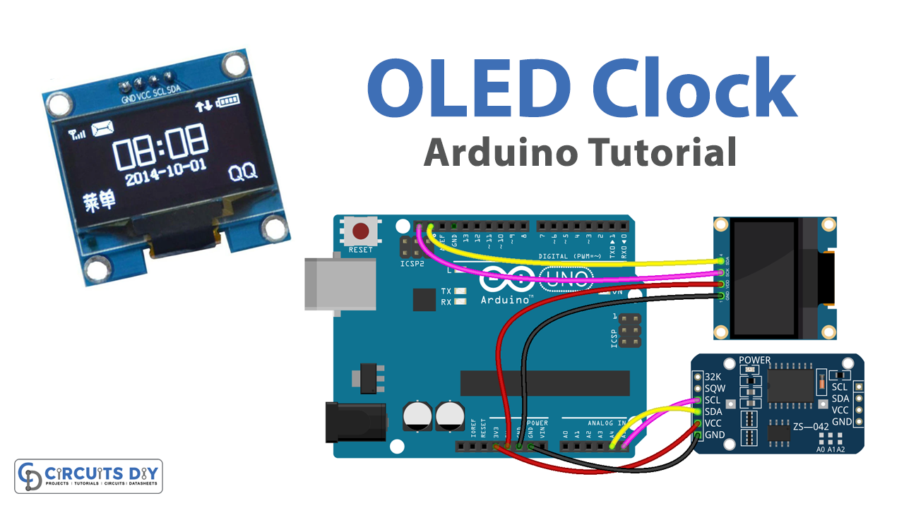
Designing a digital watch using a combination of an OLED display and a real-time clock (RTC) module is a common project among Arduino enthusiasts. The OLED display provides a clear, bright, and low-power display solution while the RTC module accurately keeps track of the time even when the main microcontroller is powered off. An Arduino UNO microcontroller is used as the main control unit to read the current time from the RTC module and display it on the OLED display. This project provides a simple and inexpensive solution for creating a digital watch that can be customized and extended to suit a wide range of applications.
A ssd1306 I2C IIC OLED Display module is a small OLED (Organic Light Emitting Diode) display that can be used for displaying text, graphics or any other visual information in a small form factor. The DS3231 RTC (Real-Time Clock) module is a timing device that provides accurate timekeeping even when the microcontroller is powered off or in sleep mode. It uses an RTC IC that is capable of counting seconds, minutes, hours, day of the week, date, month and year.
Hardware Components
You will require the following hardware for Interfacing SSD1306 OLED Clock with Arduino.
| S.no | Component | Value | Qty |
|---|---|---|---|
| 1. | Arduino | UNO | 1 |
| 2. | USB Cable Type A to B | – | 1 |
| 3. | I2C OLED Display 128×64 | SSD1306 | 1 |
| 4. | Real-Time Clock Module | DS3231 | 1 |
| 5. | Real-Time Clock Module | DS1307 | 1 |
| 6. | Battery | CR2032 | 1 |
| 7. | Power Adapter for Arduino | 9V | 1 |
| 8. | Jumper Wires | – | 1 |
SSD1306 OLED Clock with Arduino
- Start by including the required libraries at the top of the sketch:
#include <Wire.h>
#include <Adafruit_SSD1306.h>
#include <RTClib.h>
- Initialize the OLED display:
Adafruit_SSD1306 display(128, 32, &Wire);
- Initialize the RTC clock:
RTC_DS3231 rtc;
- In the
setup()function, start the I2C communication with the following code:
Wire.begin();
- Initialize the OLED display with the following code:
display.begin(SSD1306_SWITCHCAPVCC, 0x3C);
display.clearDisplay();
- Check if the RTC is running and has a valid time with the following code:
if (!rtc.begin()) {
  display.println("Couldn't find RTC");
  while (1);
}

if (!rtc.isrunning()) {
  display.println("RTC is NOT running");
  rtc.adjust(DateTime(F(__DATE__), F(__TIME__)));
}
- In the
loop()function, get the current time from the RTC with the following code:
DateTime now = rtc.now();
- Clear the OLED display and display the current time with the following code:
display.clearDisplay();
display.setCursor(0, 0);
display.println(now.hour() + ":" + now.minute() + ":" + now.second());
display.display();
- Wait for 1 second with the following code:
delay(1000);Schematic
Make connections according to the circuit diagram given below.

Wiring / Connections
| Arduino | OLED | RTC Module |
|---|---|---|
| 5V | VCC | |
| GND | GND | GND |
| SCL | SCL | |
| SDA | SDA | |
| A4 | SCL | |
| A5 | SDA | |
| 3V3 | VCC |
Installing Arduino IDE
First, you need to install Arduino IDE Software from its official website Arduino. Here is a simple step-by-step guide on “How to install Arduino IDE“.
Installing Libraries
Before you start uploading a code, download and unzip the following libraries at /Progam Files(x86)/Arduino/Libraries (default), in order to use the sensor with the Arduino board. Here is a simple step-by-step guide on “How to Add Libraries in Arduino IDE“.
Code
Now copy the following code and upload it to Arduino IDE Software.
#include <Wire.h>
#include <Adafruit_GFX.h>
#include <Adafruit_SSD1306.h>
#include <RTClib.h>

#define SCREEN_WIDTH 128 // OLED display width,  in pixels
#define SCREEN_HEIGHT 64 // OLED display height, in pixels

Adafruit_SSD1306 oled(SCREEN_WIDTH, SCREEN_HEIGHT, &Wire, -1); // // create SSD1306 display object connected to I2C
RTC_DS3231 rtc;

String time;

void setup() {
  Serial.begin(9600);

  // initialize OLED display with address 0x3C for 128x64
  if (!oled.begin(SSD1306_SWITCHCAPVCC, 0x3C)) {
    Serial.println(F("SSD1306 allocation failed"));
    while (true);
  }

  delay(2000);         // wait for initializing
  oled.clearDisplay(); // clear display

  oled.setTextSize(1);          // text size
  oled.setTextColor(WHITE);     // text color
  oled.setCursor(0, 10);        // position to display

  // SETUP RTC MODULE
  if (! rtc.begin()) {
    Serial.println("Couldn't find RTC");
    Serial.flush();
    while (true);
  }

  // automatically sets the RTC to the date & time on PC this sketch was compiled
  rtc.adjust(DateTime(F(__DATE__), F(__TIME__)));
  time.reserve(10); // to avoid fragmenting memory when using String
}

void loop() {
  DateTime now = rtc.now();

  time = "";
  time += now.hour();
  time += ':';
  time += now.minute();
  time += ':';
  time += now.second();

  oledDisplayCenter(time);
}

void oledDisplayCenter(String text) {
  int16_t x1;
  int16_t y1;
  uint16_t width;
  uint16_t height;

  oled.getTextBounds(text, 0, 0, &x1, &y1, &width, &height);

  // display on horizontal and vertical center
  oled.clearDisplay(); // clear display
  oled.setCursor((SCREEN_WIDTH - width) / 2, (SCREEN_HEIGHT - height) / 2);
  oled.println(text); // text to display
  oled.display();
}
Working Explanation
In the setup() function, the OLED display is initialized and I2C communication is started. The RTC is also checked to see if it is running, and if it is not, an error message is displayed on the OLED display.
In the loop() function, the current time is retrieved from the RTC and displayed on the OLED display. The loop() function repeats continuously, updating the time on the OLED display every second. The time on the OLED display is updated by clearing the display, printing the time information at the cursor position, and updating the OLED display with the current information.
Applications
- Personal Use
- Educational Purposes
- Prototyping
- Customizable Time-Keeping
- Portable Device
Conclusion.
We hope you have found this OLED Clock Circuit very useful. If you feel any difficulty in making it feel free to ask anything in the comment section.
Related posts:
 Interfacing GY-87 IMU MPU6050 HMC5883L BMP085 Module with Arduino
 Interface AT24C02 Two-Wire Serial EEPROM with Arduino
 Water Flow Sensor YF-S201 Interfacing with Arduino
 Interfacing BYGH403 1.65A Stepper Motor with Arduino
 How to Interface 2 DC Motors Via Bluetooth with Arduino UNO
 IR Infrared Obstacle Avoidance Sensor - Arduino Tutorial


