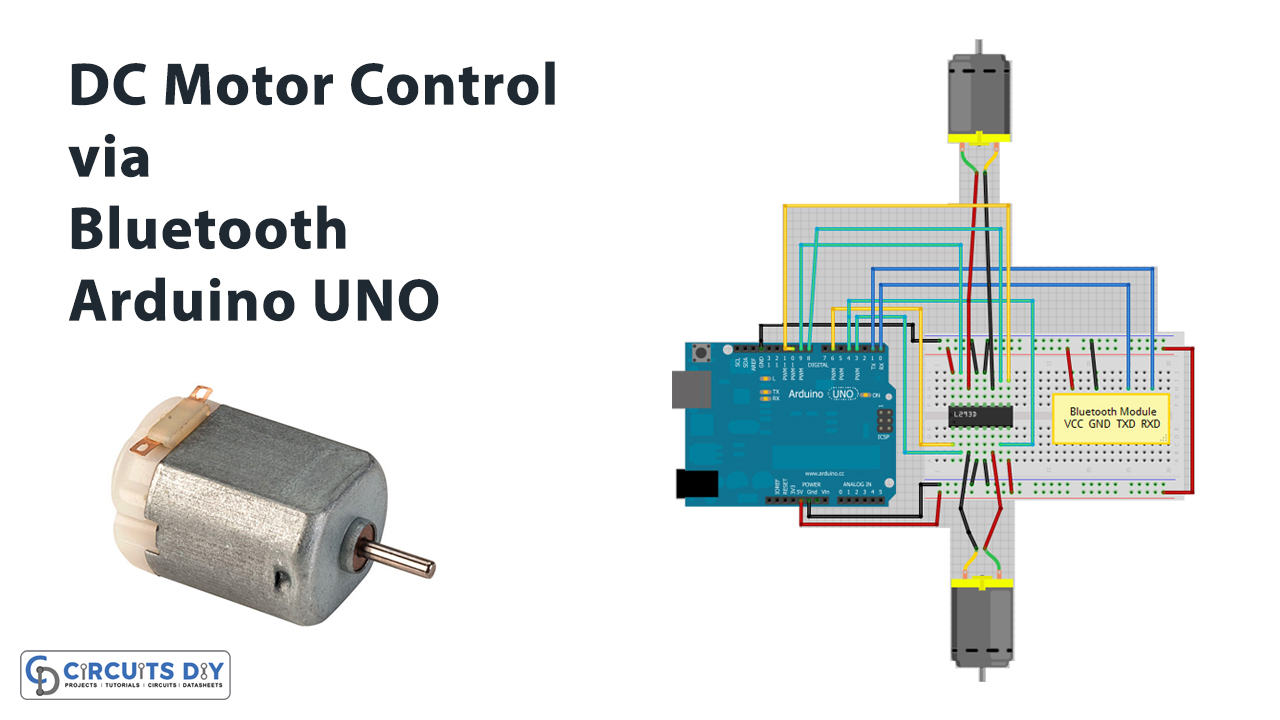
Introduction
Everyone is aware of Bluetooth. Generally, people used it on smartphones to share data. It exchanges the data through wireless connections over a short distance. You must have seen Bluetooth devices like AirPods, GPS devices, Bluetooth keyboards, etc. Some of them may contain Bluetooth modules. But have you ever controlled the motor through this Bluetooth module by interfacing it with an Arduino? This tutorial is all about that. Therefore, in this tutorial, we are going to interface “2 DC Motors Via Bluetooth with Arduino UNO”.
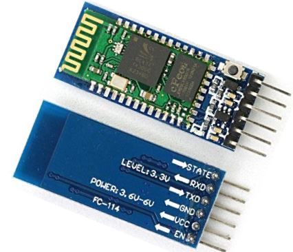
An Overview about Bluetooth Module
The HC-05 is the most common module in the market. It’s cheap and simple to use. The module has a frequency of about 2.4GHz. Further, it works on the temperature of -200C to 750C. The module has two operational modes that are, AT command mode and the connection mode. Command mode sets the command and the connection mode connects the device to another device.
Hardware Required
| S.no | Component | Value | Qty |
|---|---|---|---|
| 1. | Arduino | UNO | 1 |
| 2. | USB Cable Type A to B | – | 1 |
| 3. | Jumper Wires | – | – |
| 4. | 2 DC Motors, Bluetooth | L293D IC | – |
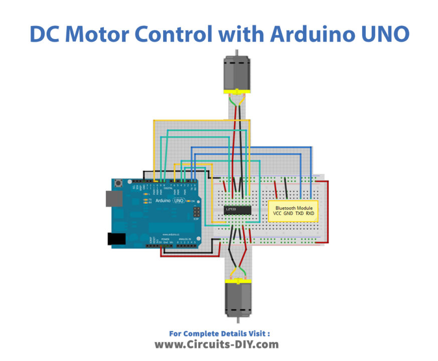
Circuit Diagram
Connections Table
Arduino Code
// Circuits DIY
 // For Complete Details Visit -> https://circuits-diy.com

int motor1Pin1 = 3; // pin 2 on L293D IC
int motor1Pin2 = 4; // pin 7 on L293D IC
int enable1Pin = 6; // pin 1 on L293D IC
int motor2Pin1 = 8; // pin 10 on L293D IC
int motor2Pin2 = 9; // pin 15 on L293D IC
int enable2Pin = 11; // pin 9 on L293D IC
int state;
int flag=0;        //makes sure that the serial only prints once the state
int stateStop=0;
void setup() {
    // sets the pins as outputs:
    pinMode(motor1Pin1, OUTPUT);
    pinMode(motor1Pin2, OUTPUT);
    pinMode(enable1Pin, OUTPUT);
    pinMode(motor2Pin1, OUTPUT);
    pinMode(motor2Pin2, OUTPUT);
    pinMode(enable2Pin, OUTPUT);
    // sets enable1Pin and enable2Pin high so that motor can turn on:
    digitalWrite(enable1Pin, HIGH);
    digitalWrite(enable2Pin, HIGH);
    // initialize serial communication at 9600 bits per second:
    Serial.begin(9600);
}

void loop() {
    //if some date is sent, reads it and saves in state
    if(Serial.available() > 0){
      state = Serial.read();
      flag=0;
    }
    // if the state is 'F' the DC motor will go forward
    if (state == 'F') {
        digitalWrite(motor1Pin1, HIGH);
        digitalWrite(motor1Pin2, LOW);
        digitalWrite(motor2Pin1, LOW);
        digitalWrite(motor2Pin2, HIGH);
        if(flag == 0){
          Serial.println("Go Forward!");
          flag=1;
        }
    }

    // if the state is 'R' the motor will turn left
    else if (state == 'R') {
        digitalWrite(motor1Pin1, HIGH);
        digitalWrite(motor1Pin2, LOW);
        digitalWrite(motor2Pin1, LOW);
        digitalWrite(motor2Pin2, LOW);
        if(flag == 0){
          Serial.println("Turn LEFT");
          flag=1;
        }
        delay(1500);
        state=3;
        stateStop=1;
    }
    // if the state is 'S' the motor will Stop
    else if (state == 'S' || stateStop == 1) {
        digitalWrite(motor1Pin1, LOW);
        digitalWrite(motor1Pin2, LOW);
        digitalWrite(motor2Pin1, LOW);
        digitalWrite(motor2Pin2, LOW);
        if(flag == 0){
          Serial.println("STOP!");
          flag=1;
        }
        stateStop=0;
    }
    // if the state is 'L' the motor will turn right
    else if (state == 'L') {
        digitalWrite(motor1Pin1, LOW);
        digitalWrite(motor1Pin2, LOW);
        digitalWrite(motor2Pin1, LOW);
        digitalWrite(motor2Pin2, HIGH);
        if(flag == 0){
          Serial.println("Turn RIGHT");
          flag=1;
        }
        delay(1500);
        state=3;
        stateStop=1;
    }
    // if the state is 'B' the motor will Reverse
    else if (state == 'B') {
        digitalWrite(motor1Pin1, LOW);
        digitalWrite(motor1Pin2, HIGH);
        digitalWrite(motor2Pin1, HIGH);
        digitalWrite(motor2Pin2, LOW);
        if(flag == 0){
          Serial.println("Reverse!");
          flag=1;
        }
    }
    //For debugging purpose
    //Serial.println(state);
}
Working Explanation
First, connect the circuit as described above in the diagram. Now, upload the above-given code in your Arduino. Also, install the Bluetooth controller application in your smartphone for the Bluetooth module. Connect the module to this application. The application has buttons in it that allow you to control and change the directions of the DC motors. When you press any button, the Bluetooth module receives the data and transfer it to the Arduino. The Arduino then collects the data and works accordingly.
Code Explanation
- In this project, you don’t require any libraries. So, you only need to define the motor driver pins that are connected with the digital pins of an Arduino.
- In the void setup, defines the output pins. And, to turn ON the motor, set the enable pins high. Then initialize the Serial communication.
- In the void loop, use the if-else statements to describe the direction of the motors. For example, if we understand the first if statement, it instructs that if pin 1 of the motor pin is high and pin 2 is low, pin 1 of motor 2 is low, and pin 2 is high. The motor will go forward. And, it prints the same on the serial monitor. Other statements in the loop would work in the same way.
Application and Uses
- It is used in robots to control their directions over a short distance.
- It may be utilized in other devices that use the motor and need wireless connections.
- With some modification, or can control other motors, like server motors, etc which help to control doors and robotic arms, etc
Related posts:
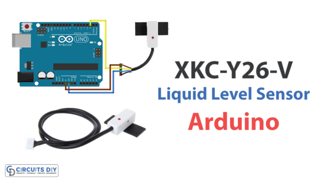 XKC-Y26-V Non-Contact Liquid Level Sensor with Arduino
 Light Sensor Triggers LED - Arduino Tutorial
 How to Interface MFRC522 RFID Reader with Arduino UNO
 Interfacing LM75 Temperature Sensor Module with Arduino
 Water Pump with Button - Arduino Tutorial
 Interfacing DX-BT18 Dual-Mode Bluetooth Module with Arduino


