Introduction
Toggling a 5V SPDT Relay module with a MC-38 Magnetic reed switch using an Arduino Uno Microcontroller is a method of controlling the state of a relay by using a magnetic reed switch as a trigger. The basic idea is to use the Arduino Uno microcontroller to read the state of the magnetic reed switch and toggle the state of the relay based on the state of the magnetic reed switch.
When the magnetic reed switch is closed, it sends a digital signal to the Arduino Uno microcontroller. The microcontroller then reads this signal and uses it to control the state of the relay. The relay can be configured to be in two states, either On or Off, and by using the toggle function, the relay will switch between these two states every time the magnetic reed switch is closed.
Hardware Components
You will require the following hardware for Door Sensor Toggle Relay with Arduino.
| S.no | Component | Value | Qty |
|---|---|---|---|
| 1. | Arduino UNO | – | 1 |
| 2. | USB Cable Type A to B | – | 1 |
| 3. | Door Sensor | – | 1 |
| 4. | Relay | – | 1 |
| 5. | Warning Light Bright Waterproof | – | 1 |
| 6. | Power Adapter | 12V | 1 |
| 7. | DC Power Jack | – | 1 |
| 8. | Power Adapter for Arduino | 9V | 1 |
| 9. | Jumper Wires | – | 1 |
Door Sensor Toggle Relay with Arduino
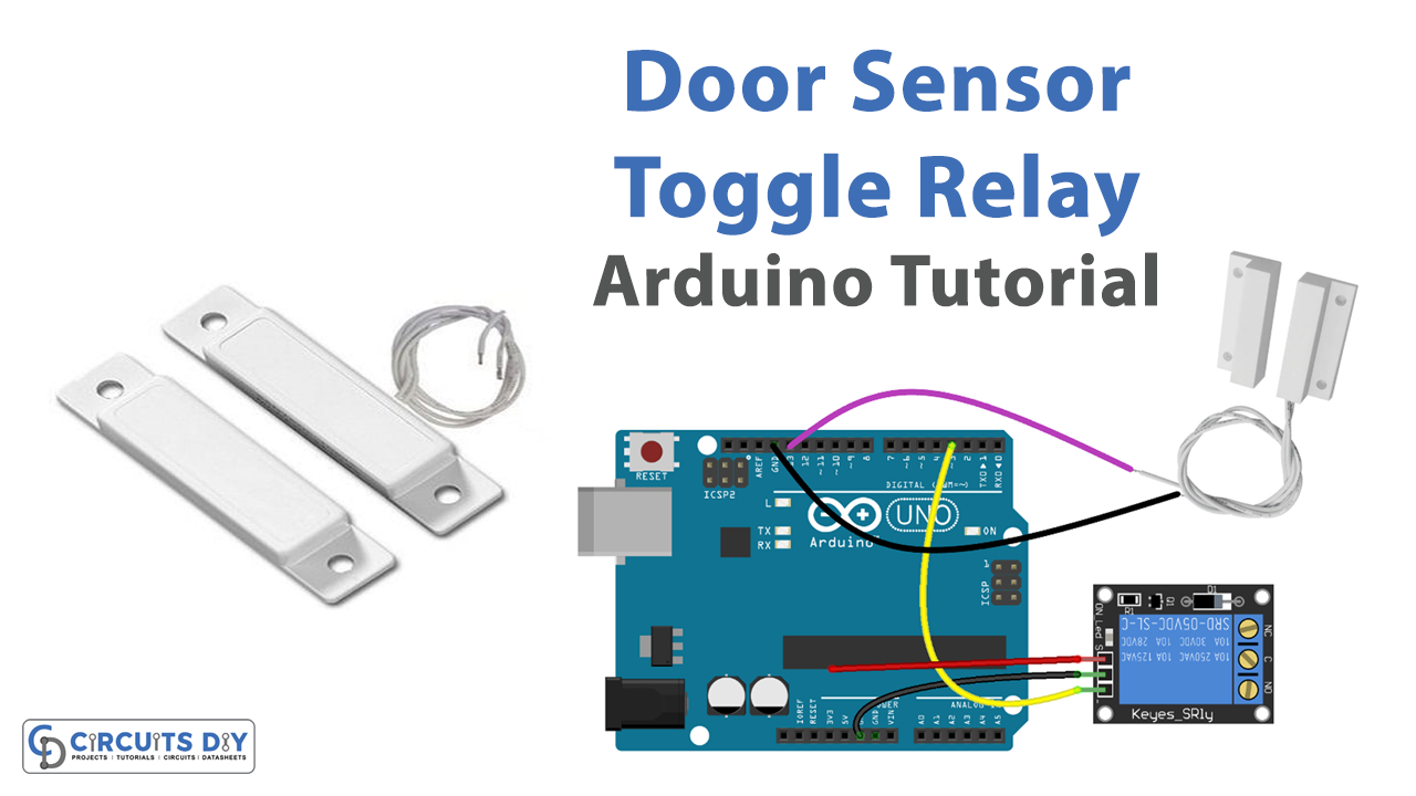
- Connect the relay module and the magnetic reed switch to the Arduino board according to the following connections:
- The relay module’s IN1 pin is connected to digital pin D2 on the Arduino board.
- One end of the magnetic reed switch is connected to digital pin D3 on the Arduino board.
- The other end of the magnetic reed switch is connected to the GND pin on the Arduino board.
- Open the Arduino IDE and create a new sketch.
- Define the pin numbers of the relay and the magnetic reed switch in the sketch:
const int relayPin = 2;
const int reedSwitchPin = 3;
- In the setup() function, initialize the serial communication and the relay and reed switch pins as inputs or outputs:
void setup() {
  Serial.begin(9600);
  pinMode(relayPin, OUTPUT);
  pinMode(reedSwitchPin, INPUT);
}
- In the loop() function, read the state of the magnetic reed switch using the digitalRead() function:
void loop() {
int reedSwitchState = digitalRead(reedSwitchPin);- In the loop() function, use an if statement to check if the reedSwitchState is LOW and if it is, then toggle the relay state using the ! operator and set the relay to the current state using digitalWrite() function:
 if (reedSwitchState == LOW) {
    relayState = !relayState;
    digitalWrite(relayPin, relayState);
  }
- Use an if statement to check the current state of the relay and print it to the serial monitor:
 if (relayState == LOW) {
    Serial.println("Relay is OFF");
  } else {
    Serial.println("Relay is ON");
  }
- Add a delay to avoid rapid switching of the relay:
delay(100);
- Close the loop and the sketch by adding a closing curly bracket:
}
- Upload the sketch to the Arduino board and open the serial monitor to check the status of the relay. The status will be toggled every time the magnetic reed switch is closed.
Schematic
Make connections according to the circuit diagram given below.

Wiring / Connections
| Arduino | Door Sensor | Relay |
|---|---|---|
| 5V | VCC | |
| GND | GND | GND |
| D13 | GIOP | |
| D3 | INP |
Installing Arduino IDE
First, you need to install Arduino IDE Software from its official website Arduino. Here is a simple step-by-step guide on “How to install Arduino IDE“.
Code
Now copy the following code and upload it to Arduino IDE Software.
int relayState = LOW; // the current state of relay
int lastDoorState;    // the previous state of door sensor
int currentDoorState; // the current state of door sensor

void setup() {
  Serial.begin(9600);                     // initialize serial
  pinMode(DOOR_SENSOR_PIN, INPUT_PULLUP); // set arduino pin to input pull-up mode
  pinMode(RELAY_PIN, OUTPUT);             // set arduino pin to output mode

  currentDoorState = digitalRead(DOOR_SENSOR_PIN);
}
Working Explanation
In the setup() function, the serial communication, and the relay and reed switch pins are initialized as inputs or outputs. In the loop() function, the microcontroller constantly reads the state of the magnetic reed switch using the digitalRead() function. When the magnetic reed switch is closed, the microcontroller reads the value LOW and toggles the state of the relay using the! operator and sets the relay to the current state using digitalWrite() function. The microcontroller also uses an if statement to check the current state of the relay and print it to the serial monitor. The status of the relay will be toggled every time the magnetic reed switch is closed.
The sketch also includes a delay to avoid rapid switching of the relay and a closing curly bracket to close the loop and the sketch. Once the sketch is written, it can be uploaded to the Arduino board and the status of the relay can be monitored by opening the serial monitor.
Applications
- Home Automation
- Security Systems
- Industrial Control
- Robotics
- Medical Devices
Conclusion.
We hope you have found this Door Sensor Toggle Relay Circuit very useful. If you feel any difficulty in making it feel free to ask anything in the comment section.