The HMC6343 three-axis compass with algorithms module from Honeywell is a fully integrated, high-end, digital compass module. It can compute and give the user a heading direction, that’s accurate within a couple of degrees. This module comes in LCC ( Leadless Chip Carrier ) package, and it’s better to play with the breakout board first. It is tilt-compensated and calibrated to handle magnetic distortions. The IC combines 3-axis magneto-resistive sensors 3-axis MEMS accelerometers, analog and digital support circuits, and a microprocessor.
Further algorithms in firmware, are required for heading computation. It can handle magnetic distortion also with better calibration. The breakout board allows for easy use of the HMC6343. All that is required, is power (3.3V @ 4.5mA in run mode) and I2C connections to a microcontroller. So that the module can receive commands, and send data back to the user.
Hardware Required
| S.no | Component | Value | Qty |
|---|---|---|---|
| 1. | Arduino UNO | – | 1 |
| 2. | USB Cable Type A to B | – | 1 |
| 3. | Jumper Wires | – | – |
| 4. | Logic Level Converter | – | 1 |
| 5. | Breakout board | HMC6343 | 1 |
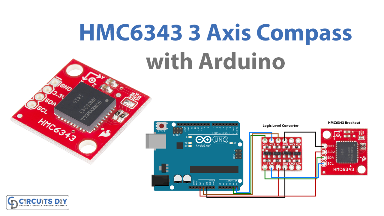
HMC6343 Circuit Diagram

Working Explanation
We will use an Arduino Uno to collect and interpret the sensor data from the HMC6343. Since the sensor uses I2C communication, all we need are two connections. One for a clock (SCL) and one for data (SDA) in addition to two for power (3.3V and GND). The Sensor HMC6343 works at a 3.3 Volt logic level, and the Arduino UNO works at a 5 Volt logic level. Here we need a logic-level converter. Then the Arduino UNO board and HMC6343 breakout board interfaced, through a bi-directional logic level converter board. We simply have to supply the accelerometer with power (3.3V and GND), then hook up the I2C connections.
The following tables show the connections made, for using the HMC6343 breakout with an Arduino Uno and logic level converter.
| Arduino UNO — | Logic Level Converter — | Logic Level Converter — |
| 3.3 V | LV | 3.3 V |
| GND | GND | GND |
| 5V | HV | N/A |
| SDA (A4) | <– HV1 LV1–> | SDA |
| SCL (A5) | <– HV2 LV2 –> | SCL |
Set up this way, I2C communication will be 3.3V on the breakout board side and 5V on the Arduino Uno side. After completing the hookup, upload the following Arduino code. And obtain the compass output at the serial monitor.
Arduino Code For HMC6343
// Libraries for I2C and the HMC6343 sensor
#include <Wire.h>
#include "SFE_HMC6343.h"

SFE_HMC6343 compass; // Declare the sensor object

void setup()
{
  // Start serial communication at 115200 baud
  Serial.begin(115200);

  // Give the HMC6343 a half second to wake up
  delay(500);

  // Initialize the HMC6343 and verify its physical presence
  if (!compass.init())
  {
    Serial.println("Sensor Initialization Failed\n\r"); // Report failure, is the sensor wiring correct?
  }
}

void loop()
{
  // Read, calculate, and print the heading, pitch, and roll from the sensor
  compass.readHeading();
  printHeadingData();

  // Read, calculate, and print the acceleration on the x, y, and z axis of the sensor
  compass.readAccel();
  printAccelData();

  // Wait for two seconds
  delay(2000); // Minimum delay of 200ms (HMC6343 has 5Hz sensor reads/calculations)
}

// Print both the raw values of the compass heading, pitch, and roll
// as well as calculate and print the compass values in degrees
// Sample Output:
// Heading Data (Raw value, in degrees):
// Heading: 3249  324.90°
// Pitch:   28    2.80°
// Roll:    24    2.40°
void printHeadingData()
{
  Serial.println("Heading Data (Raw value, in degrees):");
  Serial.print("Heading: ");
  Serial.print(compass.heading); Serial.print("  "); // Print raw heading value
  Serial.print((float) compass.heading/10.0);Serial.write(176);Serial.println(); // Print heading in degrees
  Serial.print("Pitch: ");
  Serial.print(compass.pitch); Serial.print("  ");
  Serial.print((float) compass.pitch/10.0);Serial.write(176);Serial.println();
  Serial.print("Roll: ");
  Serial.print(compass.roll); Serial.print("  ");
  Serial.print((float) compass.roll/10.0);Serial.write(176);Serial.println();
  Serial.println();
}

// Print both the raw values of the compass acceleration measured on each axis
// as well as calculate and print the accelerations in g forces
// Sample Output:
// Accelerometer Data (Raw value, in g forces):
// X: -52    -0.05g
// Y: -44    -0.04g
// Z: -1047  -1.02g
void printAccelData()
{
  Serial.println("Accelerometer Data (Raw value, in g forces):");
  Serial.print("X: ");
  Serial.print(compass.accelX); Serial.print("  "); // Print raw acceleration measurement on x axis
  Serial.print((float) compass.accelX/1024.0);Serial.println("g"); // Print x axis acceleration measurement in g forces
  Serial.print("Y: ");
  Serial.print(compass.accelY); Serial.print("  ");
  Serial.print((float) compass.accelY/1024.0);Serial.println("g");
  Serial.print("Z: ");
  Serial.print(compass.accelZ); Serial.print("  ");
  Serial.print((float) compass.accelZ/1024.0);Serial.println("g");
  Serial.println();
}
Code Explanation
Now that your electronic compass breakout is electrically connected to your Arduino, it’s time to dive into the code. To connect this HMC6343 breakout board with the Arduino board, we need a Library and you can get it here.
Once the library is installed, open the example labeled HMC6343_basics.ino. This sketch will teach you, how to get a heading direction, pitch, and roll angles as well as accelerometer measurements. The first lines of this example sketch include the necessary libraries. One for I2C, so we can declare and interact with the compass object.
Next in setup() function initialize serial communication, I2C bus, and the HMC6343. If the HMC6343 is not detected, an error message will be reported to the serial monitor. We also wait for half a second, before we try to initialize the HMC6343. Because it takes that long to be responsive after being powered on.
In the loop() function, we call two functions to read the sensor data and two more to print the data to the serial monitor in an easily readable format. compass.readHeading() is a library function, that commands the sensor to collect heading direction, pitch angle, and roll angle. And then store and printed these values in the printHeadingData() function. Here compass.readAccel() gets a reading from the IC’s 3-axis accelerometer values, and these are used and printed in printAccelData().
After calling compass.readHeading(), the variables compass.heading, compass.pitch, and compass.roll carry the heading, pitch, and roll values given by the sensor in tenths of degrees. In the printHeadingData() function, we print these raw values and also print the value converted to degrees.
If you have the breakout board parallel to the ground, the pitch and roll will be about 0 degrees. And you will see the heading angle change, as you slowly rotate the board. Try angling the board relative to the X and Y axis, and see how that affects your pitch and roll angles. Printing accelerometer values are very similar, under the printAccelData() function.
Again in the first line, we print the label. On the second line, we print the raw acceleration measurement felt on the x-axis using the variable compass.accelX. Acceleration measurements for y and z are accessed with the variables compass.accelY and compass.accelZ respectively. On the third line above, we scale the raw value by dividing it by 1024 to get the acceleration in g forces. We print that scaled value as well as the unit symbol “g”.
Application
Can be used in systems, where we need to decide direction such as GPS.