Introduction
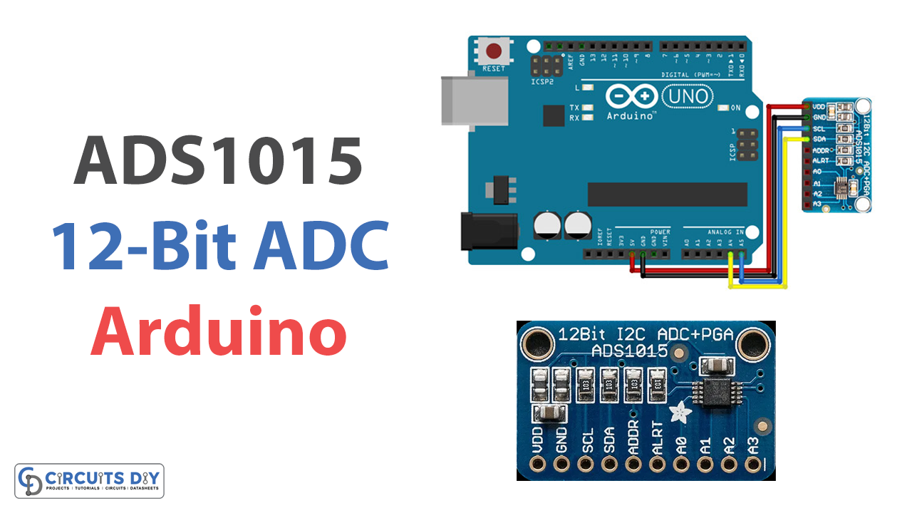
Welcome to our tutorial on interfacing the ADS1015 12-bit ADC with an Arduino microcontroller! The ADS1015 is a high-precision, low-power analog-to-digital converter that can be used to measure a variety of analog signals. It is often used in projects that need high-resolution analog measurements, like measuring temperature, pressure, or pH. This tutorial will show you how to connect the ADS1015 to your Arduino and use the Arduino to read analog input values from the ADC. We will also provide some sample code to get you started using the ADS1015 in your projects. Let’s get started!
By the end of this tutorial, you will understand how to interface the ADS1015 with an Arduino and how to use it to read and process analog signals.
What is ADC?
ADCs, which stand for “analog-to-digital converters,” are devices that convert analog signals, which have a continuous nature, into digital signals, which have a definite time and amplitude. To put it another way, an ADC takes an analog signal, such as the one picked up by a microphone, and transforms it into a digital signal.
Hardware Components
You will require the following hardware for Interfacing ADS1015 12-Bit ADC with Arduino.
| S.no | Component | Value | Qty |
|---|---|---|---|
| 1. | Arduino UNO | – | 1 |
| 2. | ADC Module | ADS1015 | 1 |
| 3. | Breadboard | – | 1 |
| 4. | Jumper Wires | – | 1 |
ADS1015 12-Bit ADC with Arduino
Once you have all the components, it’s time for the interface. And for that, you need to follow the given steps.
Schematic
Make connections according to the circuit diagram given below.
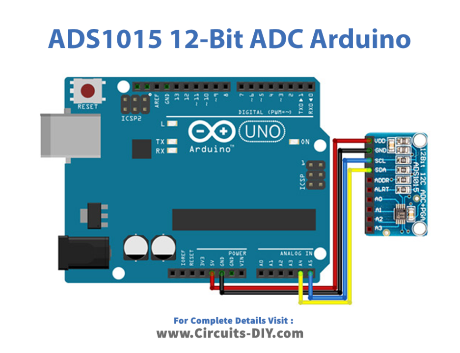
Wiring / Connections
| Arduino | Sensor |
|---|---|
| 5V | VCC |
| GND | GND |
| A4 | SDA |
| A5 | SCL |
Installing Arduino IDE
First, you need to install Arduino IDE Software from its official website Arduino. Here is a simple step-by-step guide on “How to install Arduino IDE“.
Code
Now copy the following code and upload it to Arduino IDE Software.
// test
// connect 1 potmeter per port.
//
// GND ---[   x   ]------ 5V
//            |
//
// measure at x (connect to AIN0).
//

#include "ADS1X15.h"

ADS1115 ADS(0x48);

void setup()
{
  Serial.begin(115200);
  Serial.println(__FILE__);
  Serial.print("ADS1X15_LIB_VERSION: ");
  Serial.println(ADS1X15_LIB_VERSION);

  ADS.begin();
}

void loop()
{
  ADS.setGain(0);

  int16_t val_0 = ADS.readADC(0);
  int16_t val_1 = ADS.readADC(1);
  int16_t val_2 = ADS.readADC(2);
  int16_t val_3 = ADS.readADC(3);

  float f = ADS.toVoltage(1);  // voltage factor

  Serial.print("Analog0: "); Serial.print(val_0); Serial.print('\t'); Serial.print(val_0 * f, 3);
  Serial.print("\tAnalog1: "); Serial.print(val_1); Serial.print('\t'); Serial.print(val_1 * f, 3);
  Serial.print("\tAnalog2: "); Serial.print(val_2); Serial.print('\t'); Serial.print(val_2 * f, 3);
  Serial.print("\tAnalog3: "); Serial.print(val_3); Serial.print('\t'); Serial.print(val_3 * f, 3);
  Serial.println();

  delay(1000);
}

// -- END OF FILE
*/
Let’s Test It
Now that you are done with the connection and uploading of the code, let’s test the circuit. The readings will appear on the serial monitor as soon as the Arduino is powered on.
Working Explanation
Let’s dig a little deeper into the coding to understand the working!
- In the void setup function, we start the serial monitor at 115200 baud, and the begin function is used to start the ADS1015.
- In the void loop, the gain of the ADC is set to 0 using the setGain function. This determines the range of voltages that the ADC can measure. Here we set the gain to a range of +/- 4.096V.
- The readADC function is then used to read the analog input on each of the ADC channels (0, 1, 2, and 3) and store the resulting digital values in the variables val_0, val_1, val_2, and val_3.
- The ADS.toVoltage function converts the digital values into their corresponding analog voltages. The f variable stores the voltage factor, determined by the gain setting.
- The final step is to use the Serial.print function to print the digital values and voltages to the serial monitor. The program then delays for one second before repeating the process.
Applications
- Automation and process control
- Consumer products
- Battery monitoring systems
- Temperature measurement, etc
Conclusion.
We hope you have found this Interfacing ADS1015 12-Bit ADC with Arduino Circuit very useful. If you feel any difficulty in making it feel free to ask anything in the comment section.