Introduction
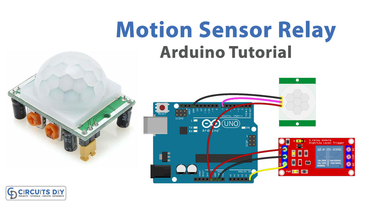
In this project, we will be using an Arduino UNO to control a 5V SPDT relay module using an HC-SR501 IR Pyroelectric Infrared PIR Module Motion Sensor, and also post the status of the relay on the serial monitor. The project can be useful in various automation applications like home automation, security systems, etc.
A PIR motion sensor, also known as a Pyroelectric Infrared sensor, is a device that detects motion by sensing changes in infrared radiation levels. The HC-SR501 IR Pyroelectric Infrared PIR Module is a popular and widely used motion sensor that can be easily interfaced with an Arduino microcontroller. When paired with a 5V SPDT relay module, this combination can be used to control various electrical devices, such as lights, fans, or alarms, based on the presence of motion
Hardware Components
You will require the following hardware for Interfacing Motion Sensor Relay with Arduino.
| S.no | Component | Value | Qty |
|---|---|---|---|
| 1. | Arduino UNO | – | 1 |
| 2. | USB Cable Type A to B | – | 1 |
| 3. | Motion Sensor | HC-SR501 | 1 |
| 4. | Relkay | – | 1 |
| 5. | Warning Light Bright Waterproof | – | 1 |
| 6. | Power Adapter | 12V | 1 |
| 7. | Power Adapter for Arduino | 9V | 1 |
| 8. | DC Power Jack | – | 1 |
| 9. | Jumper Wires | – | 1 |
Motion Sensor Relay with Arduino
- Include the necessary libraries: The first step is to include the necessary libraries for the Arduino. These libraries are required for serial communication and the HC-SR501 PIR sensor.
#include <Wire.h>
#include <PIR.h>
- Declare the pin numbers: Next, you need to declare the pin numbers for the PIR sensor and the relay module. For example, you can use pin 8 for the PIR sensor output pin and pin 9 for the relay module control pin.
#define PIR_PIN 8
#define RELAY_PIN 9
- Initialize the PIR object: Create a PIR object by passing the output pin number as an argument. This object will be used to control the PIR sensor.
PIR pir(PIR_PIN); - Write the logic in the setup() function: In the setup() function, you can start the serial communication at a specific baud rate and set the relay pin as output.
void setup() {
  Serial.begin(9600);
  pinMode(RELAY_PIN, OUTPUT);
}
- Write the logic in the loop() function: In the loop() function, you can use the PIR object’s
detectMotion()method to check the motion status. You can also use thedigitalWrite()method to control the relay module based on the motion status. Also, use theSerial.print()method to send the motion status to the serial monitor.
void loop() {
  int motion = pir.detectMotion();
  if (motion == 1) {
    digitalWrite(RELAY_PIN, HIGH);
    Serial.println("Motion detected");
  } else {
    digitalWrite(RELAY_PIN, LOW);
    Serial.println("No motion detected");
  }
  delay(1000); // delay for 1000 milliseconds
}
Schematic
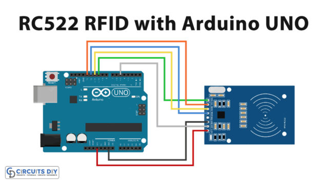
Make connections according to the circuit diagram given below.
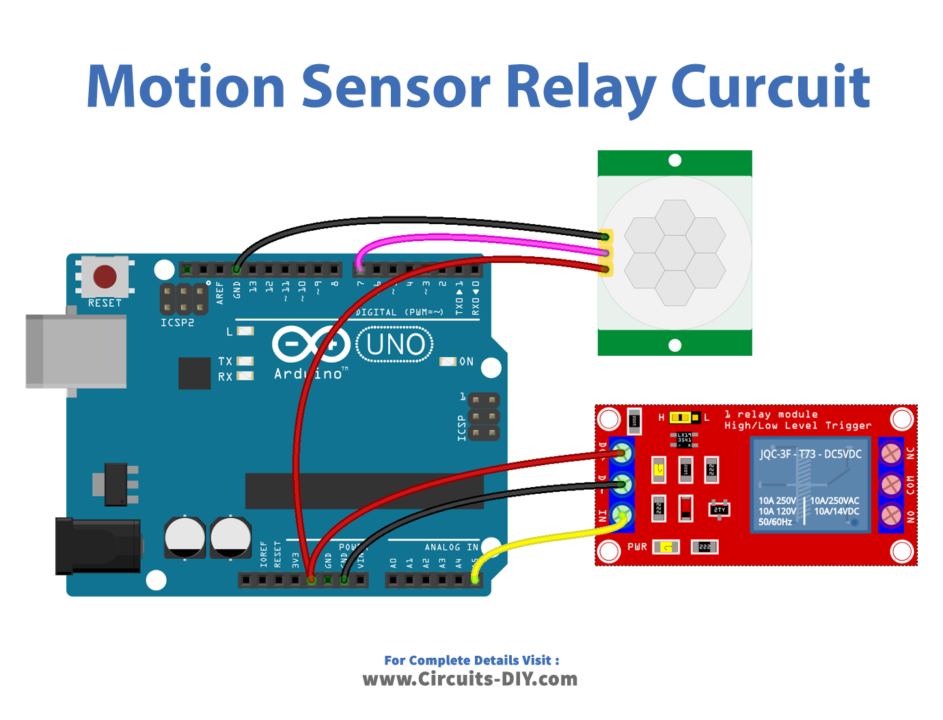
Wiring / Connections
| Arduino | Sensor | Relay |
|---|---|---|
| 5V | VCC | VCC |
| GND | GND | GND |
| D7 | OUT | |
| A5 | SIG PIN |
Installing Arduino IDE
First, you need to install Arduino IDE Software from its official website Arduino. Here is a simple step-by-step guide on “How to install Arduino IDE“.
Installing Libraries
Before you start uploading a code, download and unzip the following libraries at /Progam Files(x86)/Arduino/Libraries (default), in order to use the sensor with the Arduino board. Here is a simple step-by-step guide on “How to Add Libraries in Arduino IDE“.
Code
Now copy the following code and upload it to Arduino IDE Software.
const int MOTION_SENSOR_PIN = 7;   // Arduino pin connected to the OUTPUT pin of motion sensor
const int RELAY_PIN         = A5;  // Arduino pin connected to the IN pin of relay
int motionStateCurrent      = LOW; // current  state of motion sensor's pin
int motionStatePrevious     = LOW; // previous state of motion sensor's pin

void setup() {
  Serial.begin(9600);                // initialize serial
  pinMode(MOTION_SENSOR_PIN, INPUT); // set arduino pin to input mode
  pinMode(RELAY_PIN, OUTPUT);        // set arduino pin to output mode
}

void loop() {
  motionStatePrevious = motionStateCurrent;             // store old state
  motionStateCurrent  = digitalRead(MOTION_SENSOR_PIN); // read new state

  if (motionStatePrevious == LOW && motionStateCurrent == HIGH) { // pin state change: LOW -> HIGH
    Serial.println("Motion detected!");
    digitalWrite(RELAY_PIN, HIGH); // turn on
  }
  else
  if (motionStatePrevious == HIGH && motionStateCurrent == LOW) { // pin state change: HIGH -> LOW
    Serial.println("Motion stopped!");
    digitalWrite(RELAY_PIN, LOW);  // turn off
  }
}
Working Explanation
The code starts by including the PIR library and defining the pins for the relay and the PIR sensor. The PIR library provides functions for interacting with the HC-SR501 sensor. The relayPin is connected to digital pin 5 on the Arduino, and the PIRPin is connected to digital pin 2 (for e.g.). In the setup function, the relay pin is set as an output and serial communication is started. This allows the Arduino to send messages to the serial monitor.
In the loop function, the code checks if movement is detected by the PIR sensor by calling the detected() function on the mySensor object, which was created using the PIRPin. If movement is detected, the relay is turned on by setting the relayPin to HIGH and a message “Movement detected. Relay ON.” is displayed on the serial monitor. If no movement is detected, the relay is turned off by setting the relayPin to LOW, and a message “No movement detected. Relay OFF.” is displayed on the serial monitor.
Applications
- Security systems
- Automatic lighting
- Automated appliances
- Automated curtains or blinds
- Smart home automation
- Robotics
- Automatic Gates
Conclusion.
We hope you have found this Motion Sensor Relay Circuit very useful. If you feel any difficulty in making it feel free to ask anything in the comment section.