Introduction
Controlling WS2811 addressable LED strips with Arduino Bluetooth control using an Android app opens up a world of possibilities for creative lighting projects. With this setup, you can wirelessly control the brightness, color, and animation effects of your LED strip using a custom Android app, making it easy to customize your lighting to match your mood or setting. Whether you’re an experienced electronics hobbyist or a beginner, this setup is a fun and exciting way to explore the possibilities of addressable LED lighting.
WS2811 RGB LED strips are a type of addressable LED strip that uses the WS2811 LED driver chip. These LED strips are made up of individual RGB LEDs that are capable of producing a wide range of colors and lighting effects. Each LED has an integrated WS2811 controller chip that communicates with the Arduino or other microcontroller to receive color and brightness data.
Hardware Components
You will require the following hardware for RGB LED Control via Bluetooth.
| Components | Value | Qty |
|---|---|---|
| Arduino NANO | – | 1 |
| RGB LED Strip | WS2811 | 1 |
| Bluetooth Module | HC-05 | 1 |
| Breadboard | – | 1 |
| Jumper Wires | – | 1 |
Useful Steps
- Open the MIT App Inventor and create a new project.
- Drag and drop the following components onto the screen: BluetoothClient, Button, and Slider.
- Open the Designer view and change the properties of the components as follows:
- Set the Button’s Text property to “Red”.
- Set the Slider’s MaxValue property to 100.
- Set the Slider’s MinValue property to 0.
- Set the Slider’s ThumbPosition property to 50.
- Switch to the Blocks view and add the following code to the Screen1.Initialize block:
BluetoothClient1.Address = "your_HC-05_Bluetooth_module_address_here"
BluetoothClient1.Connect()
Replace “your_HC-05_Bluetooth_module_address_here” with the MAC address of your HC-05 Bluetooth module. 5. Add the following code to the Button.Click block:
BluetoothClient1.SendMessage("A")This will send the letter “A” to the HC-05 module, which will trigger the warm red animation on the LED strip. 6. Add the following code to the Slider.AfterChange block:
BluetoothClient1.SendMessage("B" & Slider1.ThumbPosition)This will send the letter “B” followed by the current value of the slider to the HC-05 module, which will trigger the warm blue animation on the LED strip with the desired brightness.
5. Now Open the Arduino UNO IDE and import the necessary libraries:
#include <FastLED.h>
#include <SoftwareSerial.h>
6. Define pin numbers and other constants:
#define LED_PINA    13
#define NUM_LEDS  100
SoftwareSerial mySerial(4, 5);
7. Initialize the serial interfaces in the setup() function:
void setup() {
  FastLED.addLeds<WS2812, LED_PINA, GRB>(leds, NUM_LEDS);
  mySerial.begin(9600);
  Serial.begin(9600);
}
8. Define the LED strip and animation patterns in the loop() function:
void loop() {
  if(mySerial.available()>0) {
    char m = mySerial.read();
    Serial.println(m);
    switch (m) {
      // Warm red animation
      case 'A':
        int q;
        for(q=0; q<=90; q++) {
          for (int i = 0; i <= NUM_LEDS; i++) {
            leds[i] = CRGB ( 255, 0, 0);
          }
          FastLED.setBrightness(q);
          FastLED.show();
          delay(d);
          if(mySerial.available()>0) {
            return;
          }
        }
        // Repeat with decreasing brightness
        for(q=90; q>=0; q--) {
          for (int i = 0; i <= NUM_LEDS; i++) {
            leds[i] = CRGB ( 255, 0, 0);
          }
          FastLED.setBrightness(q);
          FastLED.show();
          delay(d);
          if(mySerial.available()>0) {
            return;
          }
        }
        break;
      // Warm blue animation
      case 'B':
        int q;
        for(q=0; q<=90; q++) {
          for (int i = 0; i <= NUM_LEDS; i++) {
            leds[i] = CRGB ( 0, 255, 0);
          }
          FastLED.setBrightness(q);
          FastLED.show();
          delay(d);
          if(mySerial.available()>0) {
            return;
          }
        }
        // Repeat with decreasing brightness
        for(q=90; q>=0; q--) {
          for (int i = 0; i <= NUM_LEDS; i++) {
            leds[i] = CRGB ( 0, 255, 0);
          }
          FastLED.setBrightness(q);
          FastLED.show();
          delay(d);
          if(mySerial.available()>0) {
            return;
          }
        }
        break;
      // Handle invalid input
      default:
        Serial.println("Invalid input!");
        break;
    }
  }
}
Schematic
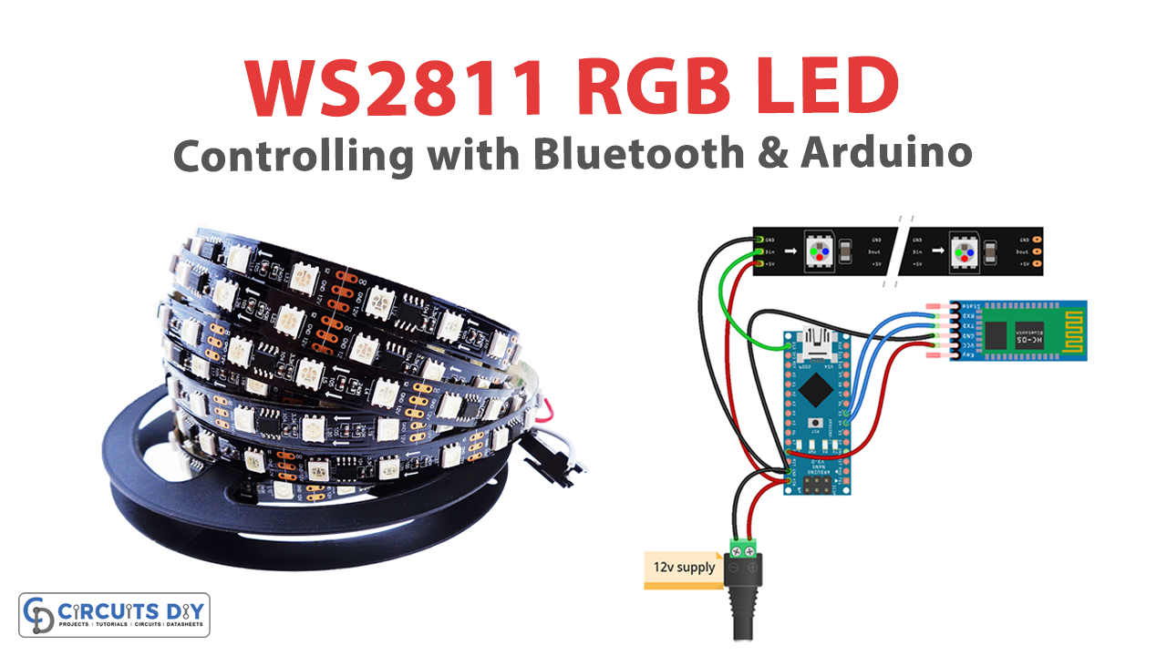
Make connections according to the circuit diagram given below.

Wiring / Connections
| Arduino NANO | WS2811 RGB LED Strip | HC-05 Bluetooth Sensor |
|---|---|---|
| VIN | 5V | |
| 5V | 5V | |
| GND | GND | GND |
| D4 | TX | |
| D5 | RX | |
| D13 | DIN |
Installing Arduino IDE
First, you need to install Arduino IDE Software from its official website Arduino. Here is a simple step-by-step guide on “How to install Arduino IDE“.
Installing Libraries
Before you start uploading a code, download and unzip the following libraries at /Program Files(x86)/Arduino/Libraries (default), in order to use the sensor with the Arduino board. Here is a simple step-by-step guide on “How to Add Libraries in Arduino IDE“.
Code
Now copy the following code and upload it to Arduino IDE Software.
#include <FastLED.h>
#include <SoftwareSerial.h>

#define LED_PINA    13
#define NUM_LEDS  100

SoftwareSerial mySerial(4, 5);

CRGB leds[NUM_LEDS];

void setup() {
  FastLED.addLeds<WS2812, LED_PINA, GRB>(leds, NUM_LEDS);
  mySerial.begin(9600);
  Serial.begin(9600);
}

void loop() {
  if(mySerial.available()>0) {
    char m = mySerial.read();
    Serial.println(m);
    switch (m) {
      // Warm red animation
      case 'A':
        int q;
        for(q=0; q<=90; q++) {
          for (int i = 0; i <= NUM_LEDS; i++) {
            leds[i] = CRGB ( 255, 0, 0);
          }
          FastLED.setBrightness(q);
          FastLED.show();
          delay(d);
          if(mySerial.available()>0) {
            return;
          }
        }
        // Repeat with decreasing brightness
        for(q=90; q>=0; q--) {
          for (int i = 0; i <= NUM_LEDS; i++) {
            leds[i] = CRGB ( 255, 0, 0);
          }
          FastLED.setBrightness(q);
          FastLED.show();
          delay(d);
          if(mySerial.available()>0) {
            return;
          }
        }
        break;
      // Warm blue animation
      case 'B':
        int q;
        for(q=0; q<=90; q++) {
          for (int i = 0; i <= NUM_LEDS; i++) {
            leds[i] = CRGB ( 0, 255, 0);
          }
          FastLED.setBrightness(q);
          FastLED.show();
          delay(d);
          if(mySerial.available()>0) {
            return;
          }
        }
        // Repeat with decreasing brightness
        for(q=90; q>=0; q--) {
          for (int i = 0; i <= NUM_LEDS; i++) {
            leds[i] = CRGB ( 0, 255, 0);
          }
          FastLED.setBrightness(q);
          FastLED.show();
          delay(d);
          if(mySerial.available()>0) {
            return;
          }
        }
        break;
      // Handle invalid input
      default:
        Serial.println("Invalid input!");
        break;
    }
  }
}
Working Explanation
The sketch defines the LED pin as pin 13 and the number of LEDs as 100. It then sets up the serial connections at a baud rate of 9600. The loop function checks for incoming serial data using the mySerial.available() function. If data is available, it reads the first character using mySerial.read() and stores it in the variable m. It then prints the character to the serial monitor using Serial.println(m).
The sketch then uses a switch statement to determine which animation to play based on the received character. If the character is ‘A’, it plays a warm red animation by gradually increasing the brightness of the LEDs from 0 to 90 and then decreasing it back to 0. If the character is ‘B’, it plays a warm blue animation using the same method. If the character is anything else, it prints an error message to the serial monitor.
In each animation case, the sketch uses a for loop to iterate through the brightness levels and set the color of each LED to the appropriate value using the CRGB function. It then sets the brightness of the LED strip using FastLED.setBrightness(q) and updates the display using FastLED.show(). It also introduces a delay between each brightness level change, controlled by a variable d, whose value is not shown in the code.
Applications
- Home automation
- Stage lighting
- Advertising and marketing
- Automotive lighting
- Industrial automation