Introduction
If you use LEDs in your circuit, you’ve probably heard or read that you should have always used a current limiting resistor. It’s essential to limit the current flowing through an LED. Higher currents flowing through any LED can destroy the LED. therefore, we have decided to make a “Current Control Circuit for LED”. Thus, this circuit was designed to generate a 1W LED array.
In the making of the circuit, we are using MAX16832 high-brightness LED driver which is a cost-effective design solution for lighting applications.
The MAX16832 has an input voltage range of +6.5 V to +65V and can deliver an output current of 700 mA if operated at +125°C or 1 A if operated at +105°C. A pulse-width modulation input allows pulsed LED dimming across a broad range of brightness levels, and a high-side current-sense resistor controls the output current.
Hardware Components
The following components are required to make the Current Control Circuit
| S.no | Component | Value | Qty |
|---|---|---|---|
| 1. | IC | MAX16832 | 1 |
| 2. | Transistor | BC547, BC557 | 1, 1 |
| 3. | Diode | 1N5819, 1N4007 | 1, 1 |
| 4. | LED | 1 Watt | 5 |
| 5. | Switch | – | 2 |
| 6. | Resistor | 2K, 100KΩ, 10KΩ, 220Ω | 1, 2, 1, 1 |
| 7. | Electrolyte Capacitor | 1uF | 2 |
| 8. | Inductor | 470uH | 1 |
| 9. | Battery | 18V | 1 |
MAX16832 Pinout
For a detailed description of pinout, dimension features, and specifications download the datasheet of MAX16832
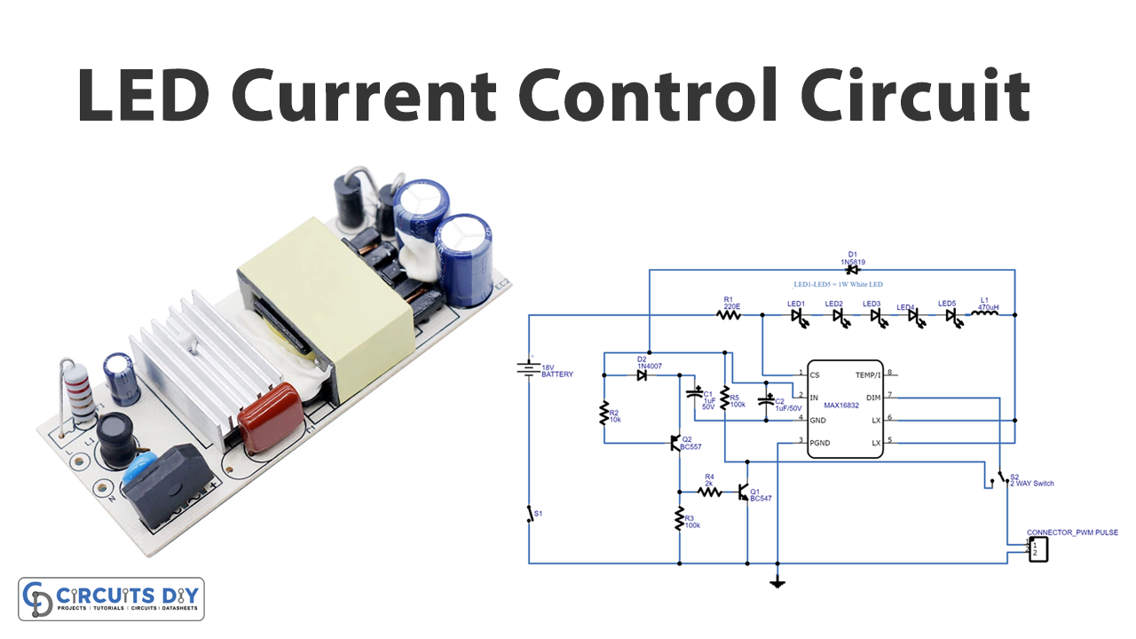
Current Control Circuit
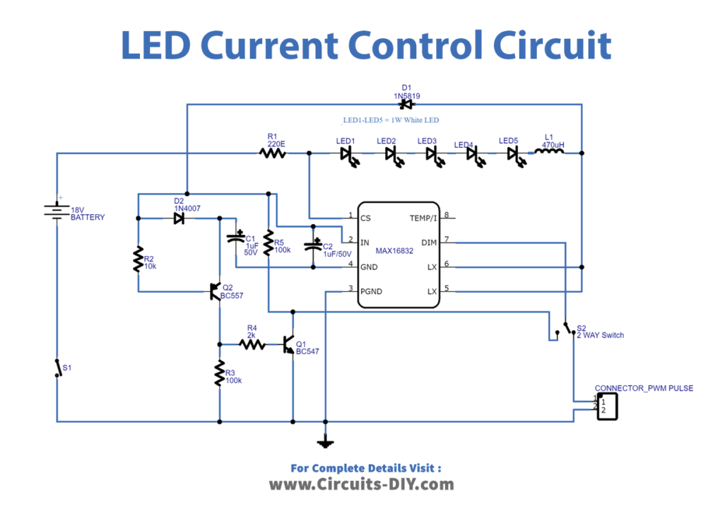
Working Explanation
This Current Control Circuit for LED is built with a PWM oscillation circuit and an alternative for external PWM input, so you may pick the PWM signal from an internal or external source, and the LED brightness level can be adjusted across a large range by altering the PWM pulse.
Application and Uses
The circuit is utilized in different LED circuits to limit the current flowing the LED.