Introduction
Have you ever seen someone mixing sounds from different microphones? They usually use a device with many microphone inputs to do that. But what if you only have a few microphones? Well, you can use a circuit called a microphone mixer circuit that has been designed just for that purpose.
In this article, we’ll be looking at a simple and beginner-friendly microphone mixer circuit. With its low power consumption and ability to work with high-impedance microphones, this circuit is perfect for portable equipment and small-scale mixing projects.
Hardware Required
| S.no | Components | Value | Qty |
|---|---|---|---|
| 1 | V.Resistor | 500k | 1 |
| 2 | Capacitor | 0.1, 0.05, 22uF | 2, 2, 2 |
| 3 | Resistor | 2M, 6.8k, 500K, 560, 100K, | 2, 2, 1, 1, 1 |
| 4 | FET Transistors | – | 1 |
Circuit Diagram

Circuit Explanation
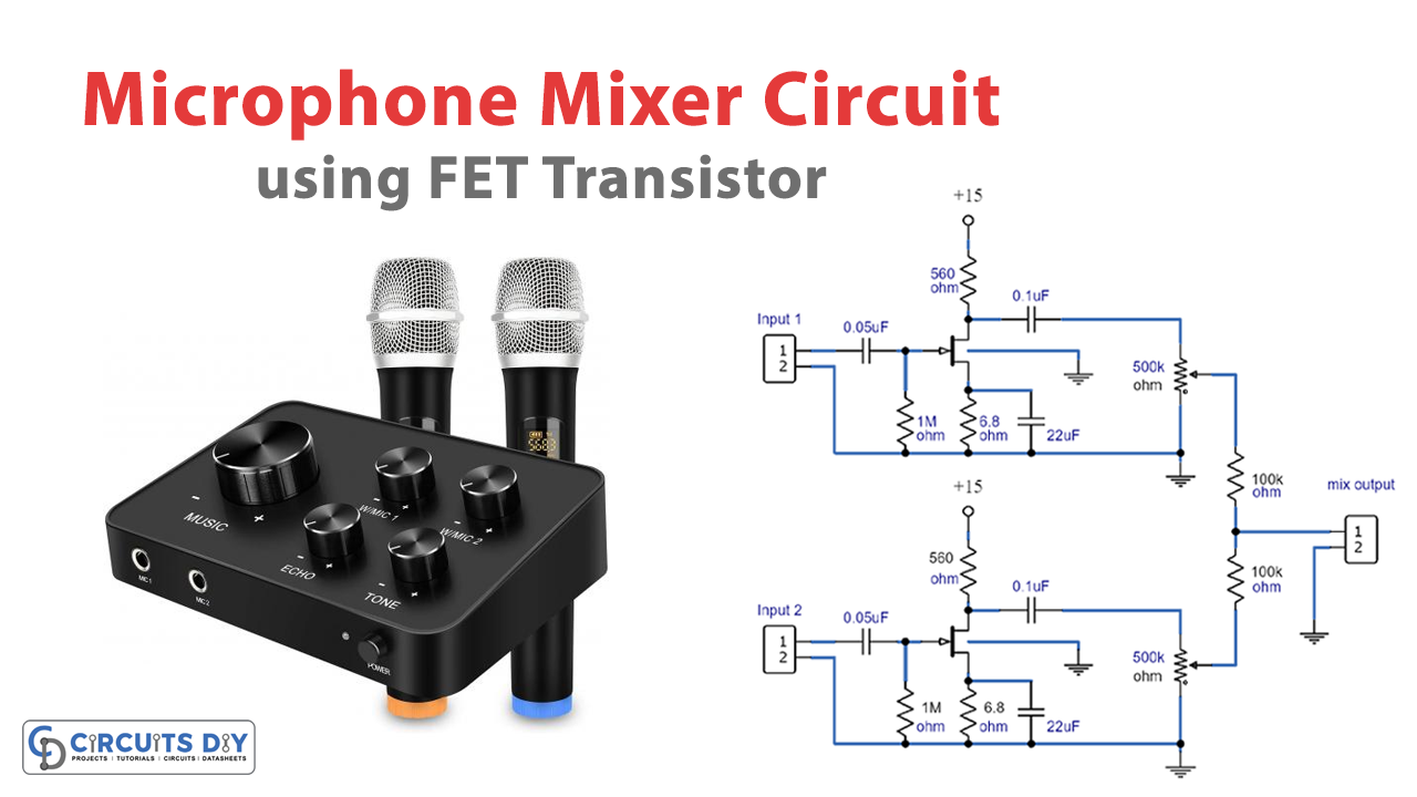
The microphone mixer circuit takes two microphone inputs and combines them into one output. It does this by first amplifying and filtering each microphone input separately. This helps to reduce any noise that might be present in the sound.
The circuit uses FET transistors that have a high input impedance. This means you can use high-impedance microphones like glass or ceramics and still get good sound quality. The volume of each microphone can be controlled separately using the potentiometers located at the output of the preamplifiers.
The best part about this circuit is that it uses very little power, just a few milliamps. This makes it perfect for portable equipment that is powered by batteries.
Conclusion
In conclusion, the microphone mixer circuit explored in this article is an excellent solution for anyone looking to mix sound from multiple microphones without investing in expensive equipment. Its simple design and low power consumption make this circuit perfect for portable equipment and small-scale projects. Following the circuit diagram, you can quickly build this microphone mixer circuit at home and start mixing sounds from multiple sources.
We hope you found this article informative and helpful. If you have any questions or queries regarding the circuit or its construction, please feel free to leave a comment below. We value your feedback and would love to hear from you. Thank you for reading!