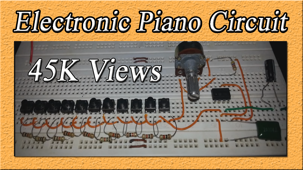
A piano is a musical instrument that produces different types of sounds when we press different buttons. In this tutorial, we will show you how to make an Electronic Piano Circuit using a 555 timer IC and some other basic electronic components.
The 555 timers will generate 5-15 different kinds of sounds. This sound depends upon the frequency of the output signal produced by the 555 timers. If you want to increase the number of tones in this circuit then connect more resistor button configurations.

Hardware Components
The following components are required to make Electronic Piano Circuit:
| S. NO | Component | Value | Qty |
|---|---|---|---|
| 1. | Breadboard | – | 1 |
| 2. | Battery | 9v | 1 |
| 3. | Connecting Wires | – | 1 |
| 4. | IC | NE555 Timer | 1 |
| 5. | Ceramic Capacitor | 100nF | 1 |
| 6. | Electrolytic Capacitor | 10uF | 1 |
| 7. | Resistors | 1k ohm | 10 |
| 8. | POT | 10K ohm | 1 |
| 9. | Push Button | – | 10 |
| 10 | Speaker | 8 ohm | 1 |
555 IC Pinout

For a detailed description of pinout, dimension features, and specifications download the datasheet of 555 Timer
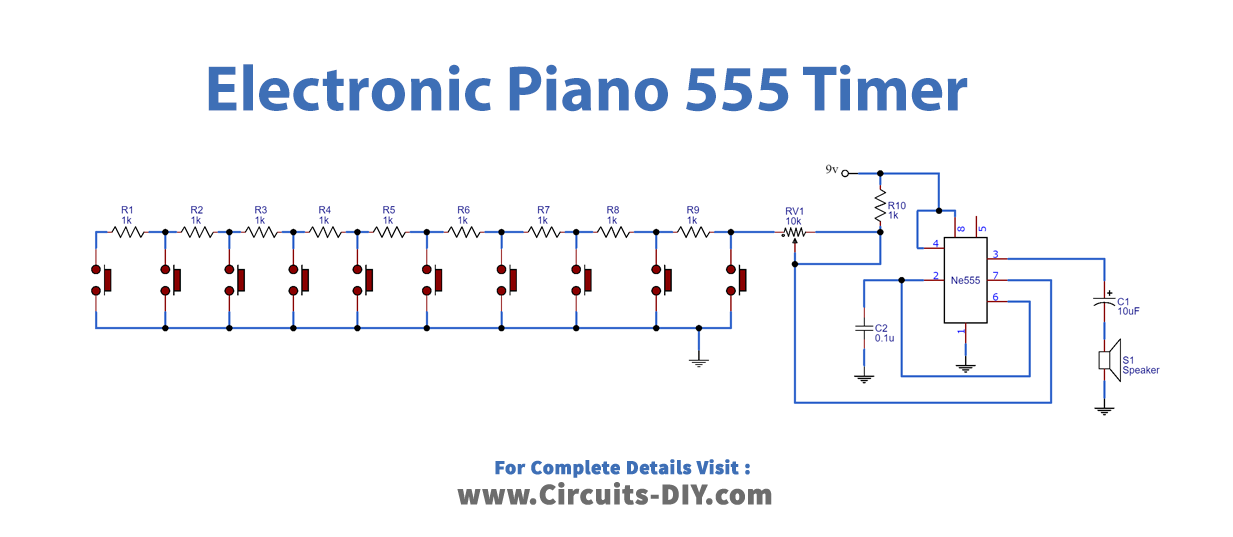
Electronic Piano Circuit
Connection
- Connect all the Pushbuttons with the 10K Resistors as shown in the circuit.
- Place the 555 timer IC on the breadboard and connect Pin 4 and Pin 8 to VCC and Pin 1 to GND.
- Connect Pin 2 and Pin 6 to the 100nF Capacitor.
- Connect the Pin 7 to the Wiper of the Potentiometer.
- The other terminals of the potentiometer will be connected to the network of pushbuttons and resistors and to the VCC.
- Connect the output pin 3 to the 10nF Capacitor and Speaker.
Working Explanation
In this circuit, the 555 timer IC will work as an Astable multivibrator producing a square wave of different frequencies at the output. The speaker will produce different sounds depending on the frequency of the signal. To change the frequency of the output signal, vary the total resistance of the circuit by pressing different switches. So every time you press a button a different amount of resistance gets connected to generate a different frequency square wave and the speaker will produce different tones.
Pin 6 and Pin 2 will allow retriggering of 555 Timer IC after every timing cycle. So we will connect these pins together to the ground through a capacitor. The output pin 3 is connected to the speaker through a 10uF capacitor and the fourth pin is connected to the VCC to avoid any sudden resets.
Application
- We can use this circuit in toys to produce different types of tones.