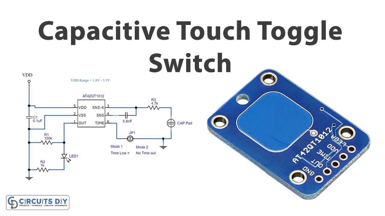
In this tutorial, we are going to make a “Capacitive Touch Toggle Switch circuit”.
The capacitive touch sensor provides a great user experience, it is easy and more convenient to use as it has no moving mechanical parts. From remote controls, and LED light controls to appliance control panels all have touch sensors because it is a simple solution to replace mechanical buttons and can be implemented in a wide variety of applications. The essence of capacitive touch sensing is the change in capacitance that occurs when an object usually a human finger approaches a capacitor, presence of a finger increases the capacitance by introducing a substance with a relatively high dielectric constant and providing a conductive surface that creates additional capacitance in parallel with the existing capacitor. As we know few electronic elements available in the market with high sensitivity and high reliability.
Here we choose the IC AT42QT1012 from Atmel, it can be employed in a circuit with a few easily available components. The AT42QT1012 is a one-channel toggle mode touch sensor IC with power management functions. It can be in toggle mode (touch -ON/ touch -OFF), or programmable auto delay mode, this IC is designed specifically for touch controls. And this device can suit almost any product needing a power switch or toggle mode-controlled functions. The circuit consumes a very low current.
Hardware Components
The following components are required to make Capacitive Touch Toggle Switch Circuit
| S.no | Components | Value | Qty |
|---|---|---|---|
| 1. | IC | AT42QT1012 | 1 |
| 2. | Resistor | 100KΩ, 4.7KΩ, 1KΩ | 1,1,1 |
| 3. | Ceramic capacitor | 0.1uF , 6.8nF | 1,1 |
| 4. | Cap pad (touchpad) | – | 1 |
| 5. | LED | – | 1 |
AT42QT1012 Pinout

For a detailed description of pinout, dimension features, and specifications download the datasheet of AT42QT1012
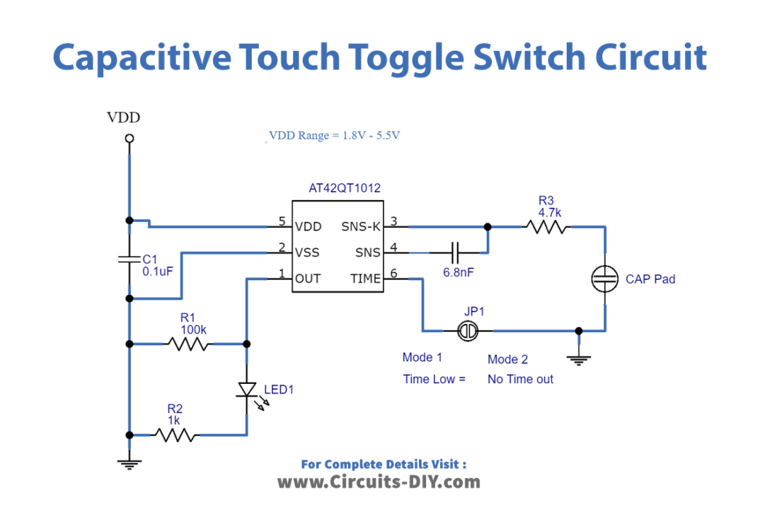
Capacitive Touch Switch Circuit
Working Explanation
First, we have to make the Cap pad (touchpad), it can be built by using a copper tape plate or any conducting material. Here the capacitor value decides the sensitivity level, a higher C2 value increases sensitivity but it takes more power and a slower reaction time, hence you can choose between the 2 – 50nF range. Now the LED is used to indicate the output, you can connect or derive any output actuator through the Out pin.
Here no microcontroller is required just power with 1.8 to 5.5VDC and touch the pad to activate the sensor. This sensor is a toggle output type: touch-on then touch-off. That means when a capacitive load is detected (e.g. a person touches the sensor-pad area) the LED will alternate turning off and the output pin will go high or low, respectively.
If you want to design this circuit in PCB you can also use a trackpad as a touch sensor, due to its proximity since it can detect touch beyond the insulator. You can also use a single or dual plate, here if you are using a dual plate means you need to separate two plates with an insulator and one plate should be connected to the ground supply.
Applications
Can be used on mobile phones, tablets, and any touch-trigger application.