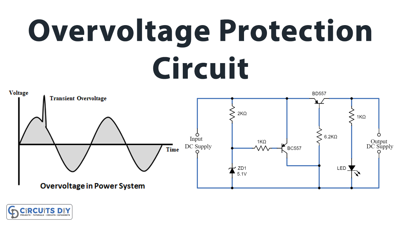
In this tutorial, we are going to make a “Simple Overvoltage Protection Circuit”.
Over-voltages are all voltages that temporarily surpass the threshold value of the mains voltage. Overvoltage protection is a power supply feature that cutoffs the supply whenever input voltage exceeds the preset value. Modern power supplies these days are very reliable, but there is always a chance of failure. A power supply can fail in many ways, but one particularly worrying possibility is the series regulator element. The electric circuits and components manufacturers always give a lot of preference and time to make it as safe as possible.
We need to provide regulated voltage for a voltage-sensitive load or electric element. In some cases, applied voltage levels may increase beyond the maximum voltage range of load. Therefore, we need to make a system to protect the load from high voltage. Here simple overvoltage protection circuit is designed by using a Zener diode and transistors. This protection circuit acts as a voltage regulator and also a circuit breaker. you can choose the Zener diode voltage range depending on your load or device voltage range, we have a 5V load and hence we have used a 5.1V Zener diode.
Hardware Component
The following components are required to make Overvoltage Protection Circuit
| S.no | Component | Value | Qty |
|---|---|---|---|
| 1. | Zener diode | 5.1V | 1 |
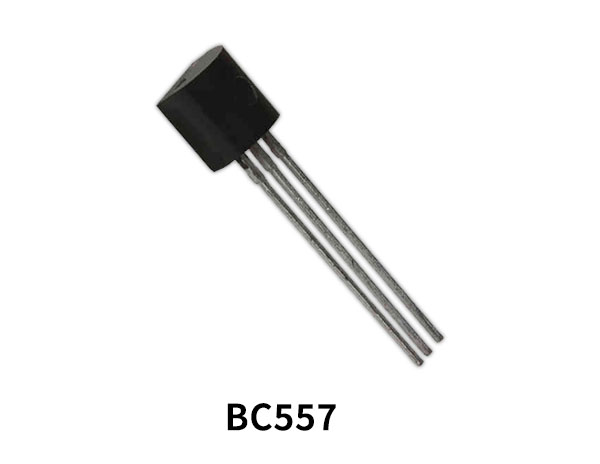
| 2. | Transistor | BC557 | 2 |
| 3. | Resistor | 2KΩ, 6.2KΩ,1KΩ | 1,1,2 |
| 4. | LED | – | 1 |
| 5. | Connecting Wires | – | – |
| 6. | Power Supply | – | 1 |
BC557 Pinout
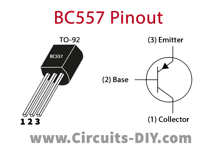
For a detailed description of pinout, dimension features, and specifications download the datasheet of BC557
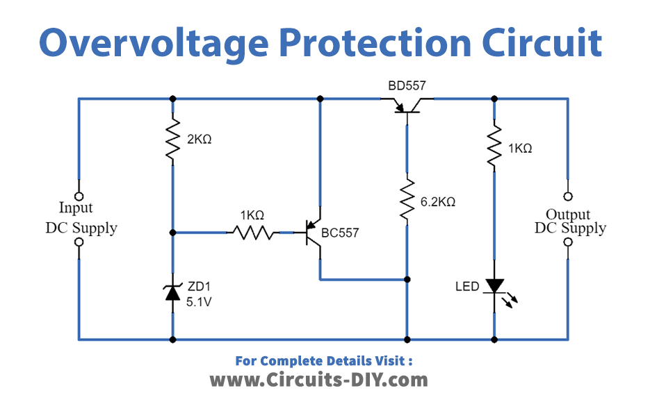
Overvoltage Protection Circuit
Working Explanation
The simple overvoltage protection circuit can be constructed with a few easily available components. The one main part of this circuit is the Zener diode first, you need to decide the regulating voltage range of the Zener diode based on the load element. The second main part is the transistor, which connects two PNP transistors with specific voltage ranges. As we have used two BC557 PNP transistors as a switch. Q1 and Q2 switching transistors are based on load element voltage and current ratings. This circuit design protects the load from limited overvoltage and has moderate current flow limiting.
When we apply DC power supply to this circuit, the reverse-biased Zener diode acts as a voltage regulator and regulated voltage flows through the Q1 transistor and to the Q2 transistor base terminal, When the voltage is less than the preset level, the base terminal of the Q1 is high and as it is a PNP transistor, it turns OFF. And, when Q1 is in off condition the base terminal of Q2 will be LOW and it allows the current to flow through it.
Now when the voltage exceeds the preset value the Zener diode starts conducting, which connects the base of Q1 to the ground and turns ON the Q1. When Q1 turns ON the base terminal of the Q2 gets HIGH and Q2 turns ON which means Q2 behaves as an Open Switch. Hence, Q2 does not allow the current to flow through it and protect the Load from exceeded voltage.
LED near the output is placed to indicate the presence of output voltage within the allowed voltage range. Use this circuit for overvoltage protection above 3.3V and below 25V load.
Applications
This circuit can be used in electrical appliances such as coffee and food processors, televisions, internet routers, and computers.