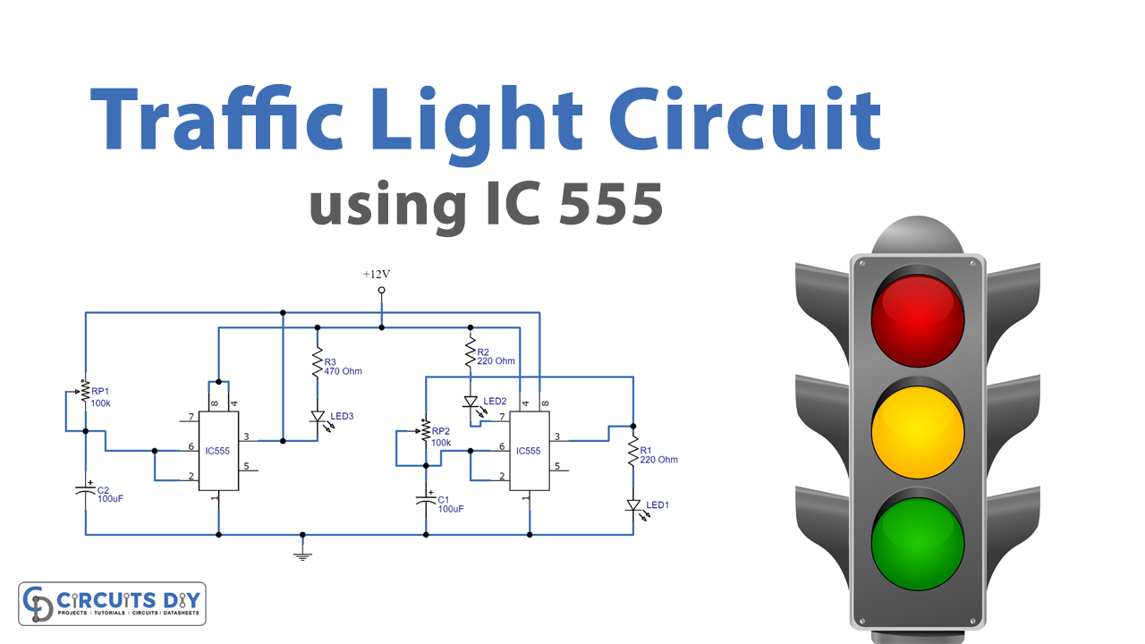
Introduction
With time, the world’s population grows, and not only the population but also the automobile industry. Several decades ago, there were far fewer automobiles on the road, and most people walked. Then came the invention of the bicycle, automobiles, and so on. And today, in the twenty-first century, the vehicle business has expanded tremendously. So, when people used to go on foot, there were no formal roads, and as automobiles became more common, roads were built as well. So, to control road traffic, the traffic light is a necessary system to use. That’s why, in this tutorial, we are going to Make a “Traffic light circuit using IC 555”.
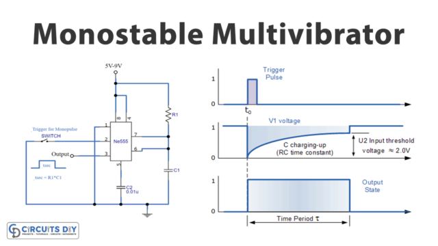
To make this circuit, we are using 555 timers Ic along with some basic electronic components. The 555timer is an integrated circuit with eight pins, This timer is utilized in the creation of pulses, oscillators, and other timing circuits. The 555 timer creates time delays in the oscillator as well as in flip-flop parts, and it has three modes: astable, bistable, and monostable.
Hardware Required
| S.no | Component | Value | Qty |
|---|---|---|---|
| 1. | IC | NE555 Timer | 2 |
| 2. | LED | – | 3 |
| 3. | Potentiometer | 100K | 2 |
| 4. | Capacitor | 100uF | 2 |
| 5. | Resistor | 220 ohms, 4700 ohms | 2, 1 |
| 6. | Battery | 12v | 1 |
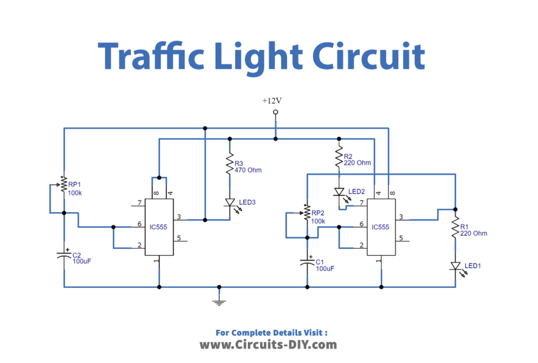
Circuit Diagram
Working Explanation
In this Traffic light circuit, we are using two 555 timer IC. The left side timer IC 555 provides an output with the help of a Red LED, while the right side timer IC 555 provides output via Yellow LED and Green LED. The yellow LED output is controlled by the discharge pin, and the VCC supply for this IC is provided through the output and timer elements of the left-side timer IC 555. We may modify the time delay between LEDs by altering the potentiometers VR1 and VR2s. LED configuration of a traffic light is depicted in the above-given circuit diagram.
Application and Uses
The circuit is particularly for traffic light systems for the regulation of vehicles.