Introduction
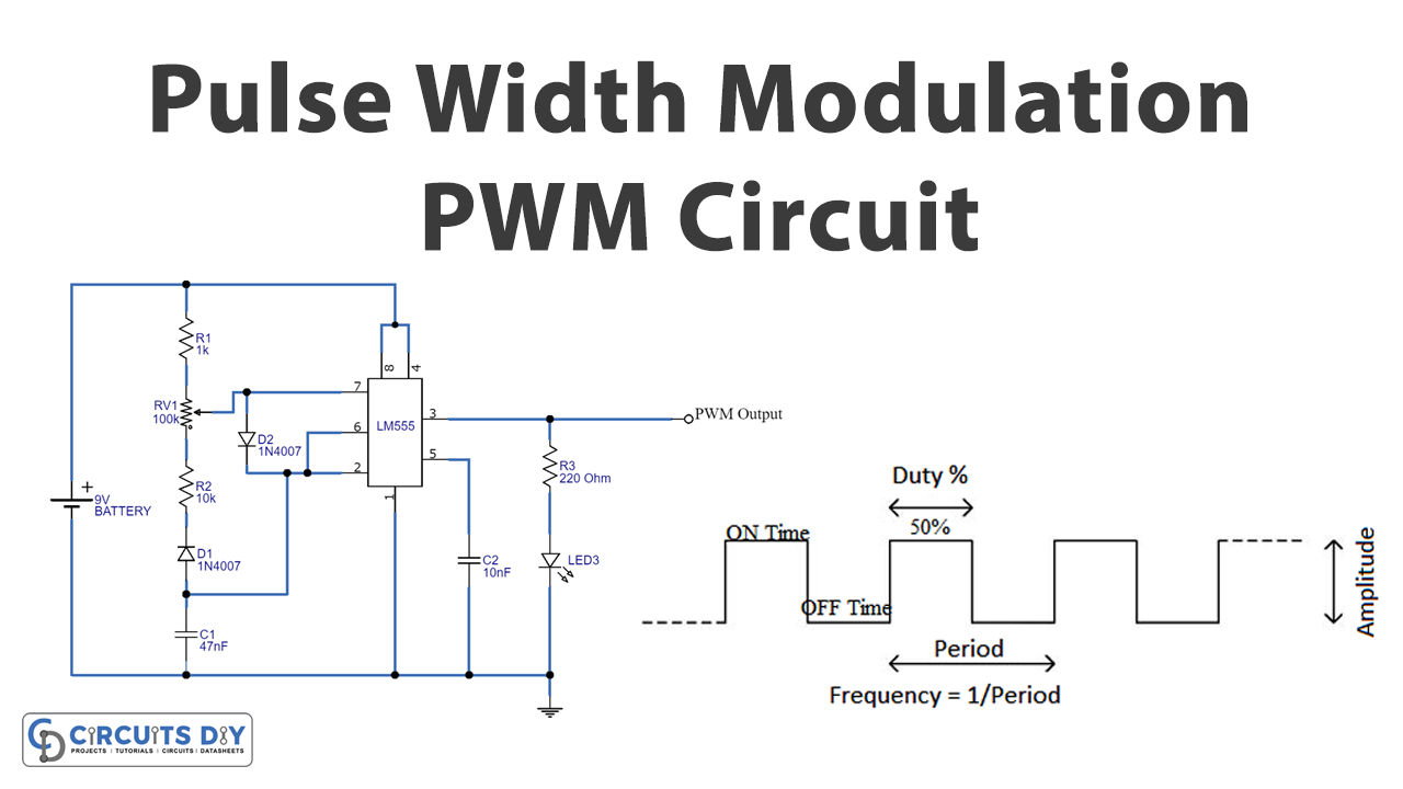
PWM is the pulse width modulation of the square wave signals that switch between ON and OFF states. Pulse Width Modulation is primarily the method that is used to reduce the average power of an electrical signal. Hence, this circuit can control the brightness of LEDs. It also has various other applications in different electronic circuits. For example, it can control the speed of the motor. To generate the pulses there is a term called duty cycle is used. The duty cycle ratio of the time when the signal is high to the total time it gets to complete one cycle. Generally expressed in percentage. To understand the whole concept, in this tutorial, we are going to ” Pulse Width Modulation Circuit”

Hardware Components
The following components are required to make PWM Circuit
| S.no | Component | Value | Qty |
|---|---|---|---|
| 1. | Timer IC | LM555 | 1 |
| 2. | Diode | 1N4007 | 2 |
| 3. | LED | – | 1 |
| 4. | Potentiometer | 100KΩ | 1 |
| 5. | Ceramic Capacitor | 47nF, 10nF | 1, 1 |
| 6. | Resistor | 1K, 10KΩ, 220Ω | 1, 1, 1 |
| 7. | Battery | 9V | 1 |
LM555 IC Pinout
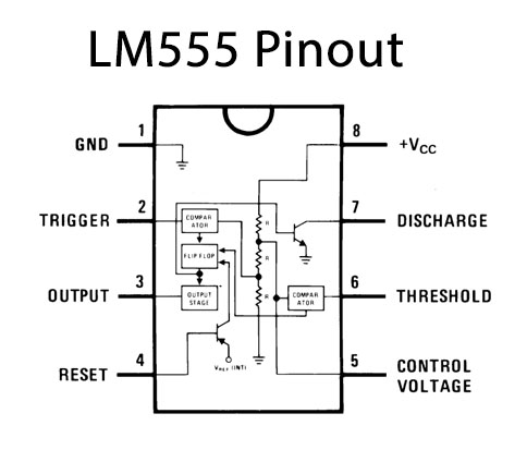
For a detailed description of pinout, dimension features, and specifications download the datasheet of LM555
PWM Circuit
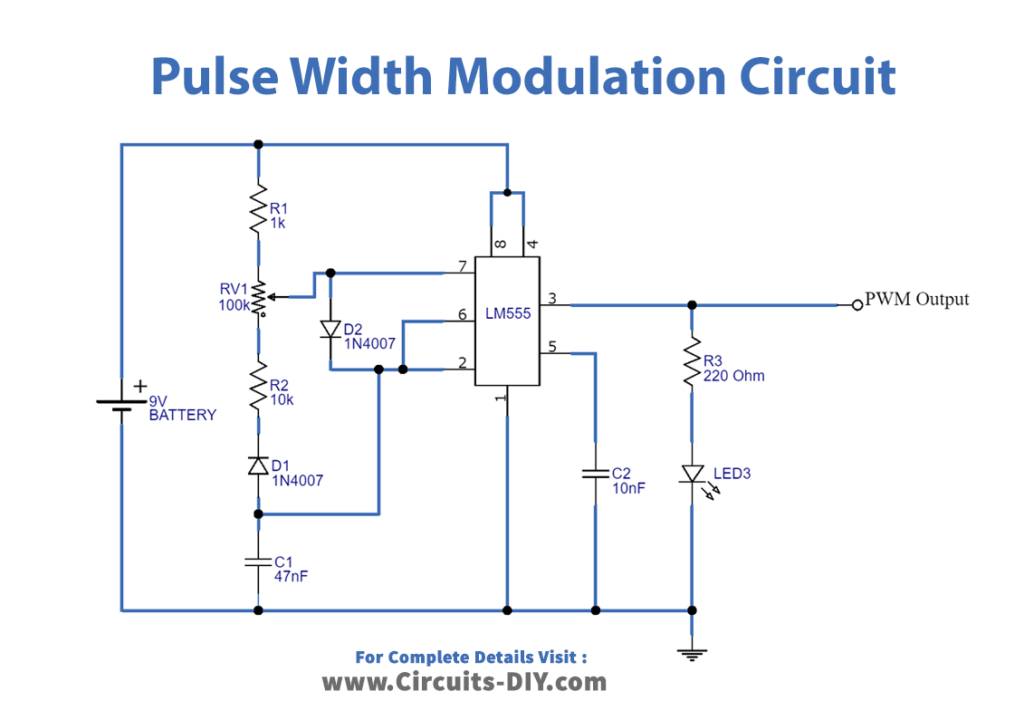
Working Explanation
In this Pulse width modulation circuit, we have used the 555 timer IC that we wired to produce a PWM signal at the output at different duty cycles. The timer 555 is configured in astable multivibrator mode and output PWM is received for a continuous square wave pulse. The width of a pulse depends on the amplitude signal. Hence potentiometer is there in the circuit that can change the output frequency. The output is taken at pin three of 555 IC.
Application and Uses
- It can use to control the speed of a DC motor.
- Also, to adjust the direction of the servo motor.
- Moreover, to change the light intensity of LEDs.
- Further, to generate audio signals.
- And, telecommunication devices to encode messages.