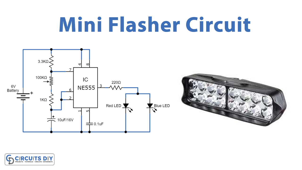
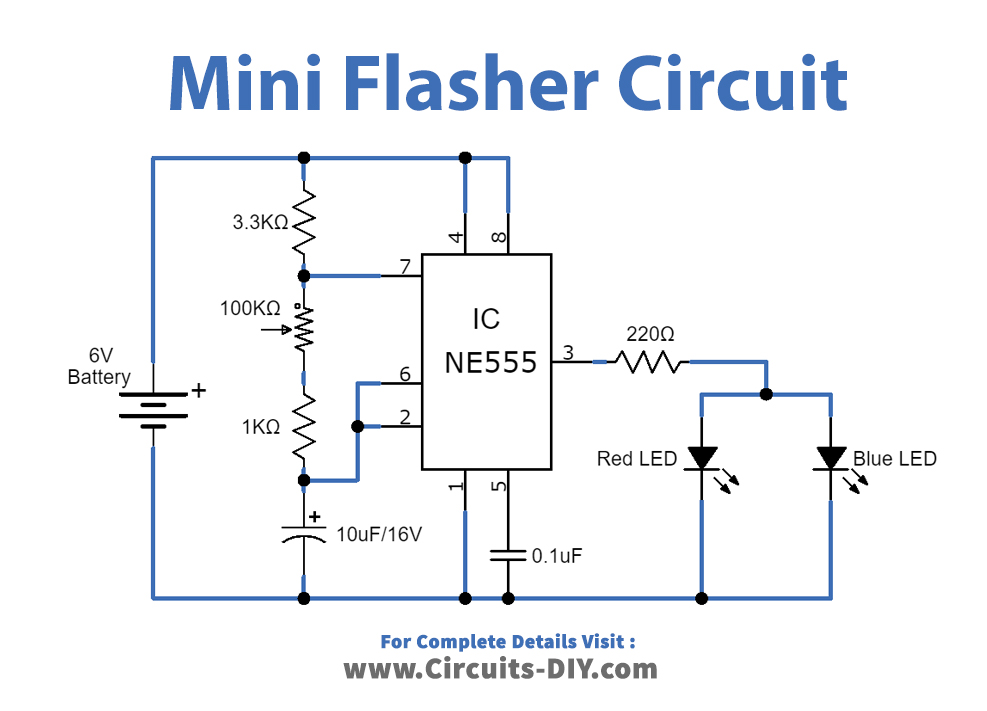
In this tutorial, we are going to make a “Mini Flasher”.
An LED flasher circuit is a circuit that flashes the LED- meaning turns it ON-OFF continuously with a specific period. We will make this led mini flasher by using timer IC LM555 and two LEDs. The 555 timer is a versatile IC because when connected correctly, it can create pulses of current at specific time intervals decided by the resistor-capacitor (RC) network. When a 555 timer creates pulses in this way, the LED doesn’t stay constantly on. It only turns on at a pulse and then shuts off after the pulse has passed. And it does this in a never-ending cycle, which creates flashes of light.
According to the timer IC output, two LEDs glow alternatively, we can adjust the blinking speed of LEDs by using the variable Resistor. This Mini Flasher circuit works like an astable multivibrator and gives continuous square pulse output, it can operate by using 6 volts to 10 volts power source.

Hardware Components
The following components are required to make Mini Flasher Circuit
| S.no | Component | Value | Qty |
|---|---|---|---|
| 1. | IC | NE555 Timer | 1 |
| 2. | Resistor | 220Ω,3.3KΩ,1KΩ | 1,1,1 |
| 3. | Electrolyte Capacitor | 10µF/16V | 1 |
| 4.. | Ceramic Capacitor | 0.1µF | 1 |
| 5. | Potentiometer | 100KΩ | 1 |
| 6. | LED | – | 2 |
| 7. | Connecting Wires | – | 1 |
| 8. | Power Supply | 6V | 1 |
NE555 IC Pinout

For a detailed description of pinout, dimension features, and specifications download the datasheet of 555 Timer
Mini Flasher Circuit
Working Explanation
The IC is connected as an astable multivibrator with a specific duty cycle, the output of a 555 timer are square waves. The duty cycle is very important for an application like this flasher circuit, duty cycle we choose determines how long the LED will stay on as compared to how long it is off.
Formulas to determine values of components in our circuit according to the needed duty cycle is:
Period = TH + TL = 0.693 (R2 + 2 R1) C
Frequency = 1.44 / (R2 + 2 R1) C
TH = 0.693 (R2 + R1) C
TL =0.693R1 C
TL = The length of time square wave is low.
TH = The length of time square wave is high.
The amount of time that the square wave is high is its duty cycle. So, for example, if the total time of a square wave is 1 second and it’s high for 0.3s, it has a duty cycle of 30%, because it’s on for only 30% of the cycle.
When we apply power to the circuit, timer IC LM555 starts to oscillate square pulse. As the duty cycle of the pulse is depending on the value of RV1 and C1, by varying RV1 we can get a different range of duty cycles. At the output terminal, two LEDs are connected through R3 Resistor, and these two LEDs are connected in an antiparallel way. Hence for both positive and negative cycle output LEDs will glow alternatively.
Applications
Generally, this circuit is used in toys for flashing lights or siren effects.
This is also useful for warning devices or as a source for square wave generation. With slight modifications in the circuit.