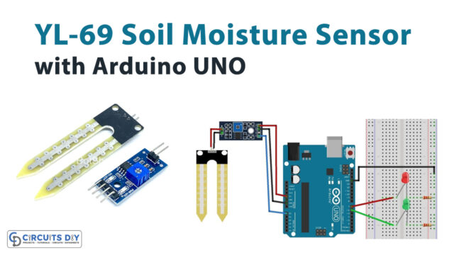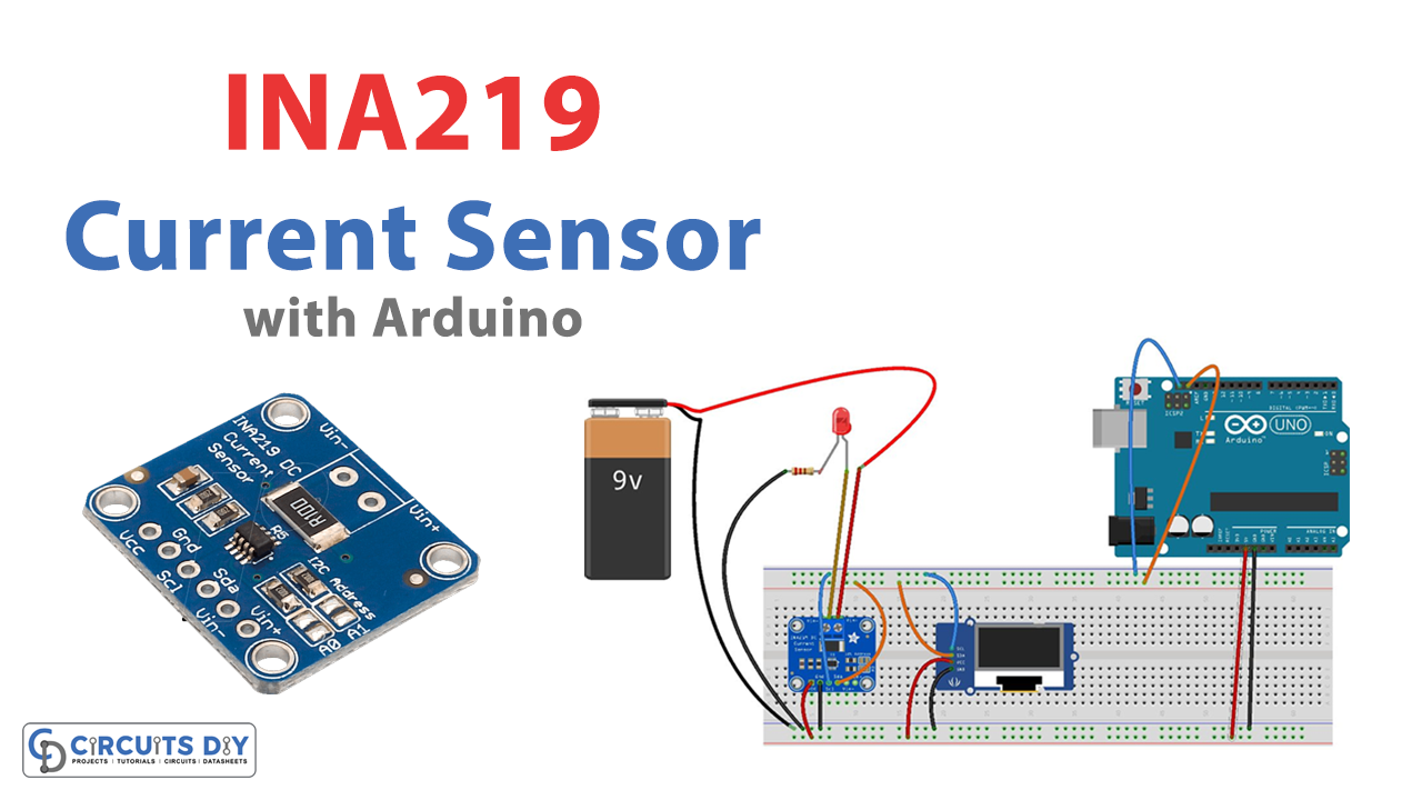
In this tutorial, we are going to “interface INA219 Current Sensor Module with Arduino” A current sensor is a device that detects electrical current, whether it is high or low, in a wire or a system and generates an indication according to it. It might then be applied to display the measured current in an ammeter, archive it for later categorization in a data collecting system, or use it for control.
INA219 Current Sensor Module
Texas Instruments launched the INA219 shunt Current Sensor module. It is a bidirectional, zero-drift power monitor module that measures shunt voltage, bus voltage, current, and power. It features a built-in 12C or SMBus interface for communicating data to the microcontrollers. The device has a 12-bit analog-to-digital converter and 16 programmable addresses enabling flexible design. It has an extra multiplier register for converting power to watts. It’s a compact, low-power current sensor module used for small embedded applications.
Hardware Overview
An INA219 chip, an I2C Bus, and a Current Sensing Resistor make up the module.
- By monitoring the voltage drop across a shunt resistor, the module may measure current, voltage, and power. It may be changed to suit your needs.
- The whole signal and data processing is carried out by the integrated circuit.
- SDA and SCL make up the I2C bus, which connects the microcontroller and the module to transfer data.
Features
- Operational Voltage: 3 – 5.5 Volts
- Operating Temperature: -400C – 1250C
- Maximum Voltage: 6 Volts
- Bus Voltage Range: 0 – 26 Volts
- Current sensing Range: ±3.2A with ±0.8mA resolution
- 0.1 ohm 1% 2W current sense resistor
Pinouts

| Pin Name | Description |
|---|---|
| A1 | Address one pin |
| A0 | Address zero pin |
| SDA | Serial data |
| SCL | Serial Clock |
| VS | Power supply pin |
| GND | Ground pin |
| IN- | positive analog input |
| IN+ | Negative analog pin |
Hardware Required
| S.no | Components | Value | Qty |
|---|---|---|---|
| 1 | Arduino UNO | – | 1 |
| 2 | USB Cable Type A to B | – | 1 |
| 3 | OLED Display Module | – | 1 |
| 4 | Jumper Wires | – | – |
| 5 | Current Sensor Module | 1NA219 | 1 |
| 6 | Bread Board | – | 1 |
| 7 | Resistor | – | 1 |
| 8 | LED | – | 1 |
| 9 | Battery | 9v | 1 |
Circuit Diagram

Connection Table
| 16X2 LCD | Arduino |
|---|---|
| 5v | Vcc |
| GND | GND |
| RS | 4 |
| VEE | POT (Middle Leg) |
| VSS | Ground |
| VDD | +5V |
| D+ | +5V |
| D- | Ground |
Arduino Code
#include <Wire.h>
#include <Adafruit_INA219.h>
#include <Adafruit_SSD1306.h>
Adafruit_INA219 ina219;

#define OLED_RESET 4
Adafruit_SSD1306 display(OLED_RESET);

float shuntvoltage = 0;
float busvoltage = 0;
float current_mA = 0;
float power_mW = 0;


void setup() {

  // initialize ina219 with default measurement range of 32V, 2A
  ina219.begin();

  // ina219.setCalibration_32V_2A();    // set measurement range to 32V, 2A  (do not exceed 26V!)
  // ina219.setCalibration_32V_1A();    // set measurement range to 32V, 1A  (do not exceed 26V!)
  // ina219.setCalibration_16V_400mA(); // set measurement range to 16V, 400mA

  // initialize OLED display
  display.begin(SSD1306_SWITCHCAPVCC, 0x3C);
  display.clearDisplay();
  display.setTextColor(WHITE);
  display.setTextSize(1);
  display.display();

}

void loop() {

  // read data from ina219
  shuntvoltage = ina219.getShuntVoltage_mV();
  busvoltage = ina219.getBusVoltage_V();
  current_mA = ina219.getCurrent_mA();
  power_mW = ina219.getPower_mW();

  // show data on OLED
  display.clearDisplay();

  display.setCursor(0, 0);
  display.print(busvoltage);
  display.print(" V");

  display.setCursor(50, 0);
  display.print(shuntvoltage);
  display.print(" mV");

  display.setCursor(0, 10);
  display.print(current_mA);
  display.print(" mA");

  display.setCursor(0, 20);
  display.print(power_mW);
  display.print(" mW");

  display.display();

}
Working Explanation
First, interface INA219 Current Sensor Module with Arduino, follow the diagram, and upload the code in Arduino. Now, the Current Sensor measures the load’s shunt voltage, bus voltage, current, and power. The data will be sent to the controller. The Arduino transfers the information to the SSD1306 OLED via the I2C protocol, and the measurements are displayed on the screen.
Code Explanation
- First, we added the Adafruit INA219 and Adafruit SSD1306 libraries for connecting the INA219 module and the OLED display, respectively. Then we made two objects: ina219 to communicate with the INA219 Current Sensor module and OLED RESET to communicate with the OLED display. Variables are initialized to hold their values.
- The void setup will configure and calibrate the INA219 Current Sensor up to the specified limit. We cannot exceed more than 26 Volts owing to designed ratings. It also turns on the OLED display.
- The void loop will simply display on the OLED screen the values received by the Arduino via the chip via the inter-integrated interface and transmitted to the OLED screen for display.
Application and Uses
- Communication systems
- Servers
- Chargers, etc