Introduction
A TTP224 4-Channel Capacitive Touch Sensor controlled Buzzer using an Arduino UNO MCU is a system that uses the Tolako TTP224 4-Channel Capacitive Touch Sensor to detect touch on four different channels and uses that information to control a 5V piezoelectric buzzer. This system can be used in a variety of applications, such as interactive exhibits and displays, smart home devices, and touch-controlled musical instruments
The Tolako TTP224 4-Channel Capacitive Touch Sensor is a touch sensor that can detect the presence of touch on four different channels, it’s a low-cost and widely used sensor that can be easily integrated into a variety of projects. The 5V piezoelectric buzzer, on the other hand, is a simple but powerful audio output device that can generate different tones depending on the input signal.
Hardware Components
You will require the following hardware for Touch Sensor Piezo Buzzer with Arduino.
| S.no | Component | Value | Qty |
|---|---|---|---|
| 1. | Arduino UNO | – | 1 |
| 2. | USB Cable Type A to B | – | 1 |
| 3. | Touch Sensor | – | 1 |
| 4. | Piezo Buzzer | – | 1 |
| 5. | Power Adapter for Arduino | 9V | 1 |
| 6. | Breadboard | – | 1 |
| 7. | Jumper Wires | – | 1 |
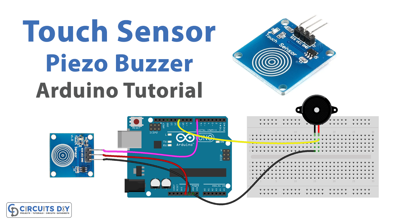
Touch Sensor Piezo Buzzer with Arduino
- Connect the Tolako TTP224 4-Channel Capacitive Touch Sensor to your Arduino UNO. Connect the VCC pin to 3.3V, the GND pin to GND, the S1 pin to digital pin 2, the S2 pin to digital pin 3, the S3 pin to digital pin 4, and S4 pin to digital pin 5.
- Connect the 5V piezoelectric buzzer to your Arduino UNO. The positive pin should be connected to digital pin 6, and the negative pin should be connected to GND.
- In the Arduino IDE, import the necessary libraries by adding these lines at the top of your sketch:
#include <SoftwareSerial.h>
- In the setup() function, configure the digital input pins connected to the Capacitive Touch Sensor as inputs and the digital output pin connected to the buzzer as output. Also, initialize the serial monitor with a baud rate of your choice:
pinMode(2, INPUT);
pinMode(3, INPUT);
pinMode(4, INPUT);
pinMode(5, INPUT);
pinMode(6, OUTPUT);
Serial.begin(9600);
- In the loop() function, read the state of the Capacitive Touch Sensor using the digitalRead() function. If a touch is detected on a specific channel, turn on the buzzer using the digitalWrite() function and send a message to the serial monitor indicating that touch has been detected on that channel. If no touch is detected, turn off the buzzer and send a message to the serial monitor indicating that there is no touch.
int touch1 = digitalRead(2);
int touch2 = digitalRead(3);
int touch3 = digitalRead(4);
int touch4 = digitalRead(5);
if(touch1 == LOW){
  digitalWrite(6, HIGH);
  Serial.println("Touch detected on channel 1!");
} else if (touch2 == LOW){
    digitalWrite(6, HIGH);
    Serial.println("Touch detected on channel 2!");
} else if (touch3 == LOW){
    digitalWrite(6, HIGH);
    Serial.println("Touch detected on channel 3!");
} else if (touch4 == LOW){
    digitalWrite(6, HIGH);
    Serial.println("Touch detected on channel 4!");
} else {
    digitalWrite(6, LOW);
    Serial.println("No touch detected.");
}
- Upload the code to your Arduino UNO and open the serial monitor to see the status of the Capacitive Touch Sensor.
Schematic
Make connections according to the circuit diagram given below.

Wiring / Connections
| Arduino | Touch Sensor |
|---|---|
| 5V | VCC |
| GND | GND |
| D7 | SIG |
Installing Arduino IDE
First, you need to install Arduino IDE Software from its official website Arduino. Here is a simple step-by-step guide on “How to install Arduino IDE“.
Code
Now copy the following code and upload it to Arduino IDE Software.
const int TOUCH_SENSOR_PIN = 7; // Arduino pin connected to touch sensor's pin
const int BUZZER_PIN       = 3; // Arduino pin connected to Buzzer's pin

void setup() {
  Serial.begin(9600);               // initialize serial
  pinMode(TOUCH_SENSOR_PIN, INPUT); // set arduino pin to input mode
  pinMode(BUZZER_PIN, OUTPUT);      // set arduino pin to output mode
}

void loop() {
  int touchState = digitalRead(TOUCH_SENSOR_PIN); // read new state

  if (touchState == HIGH) {
    Serial.println("The sensor is being touched");;
    digitalWrite(BUZZER_PIN, HIGH); // turn on Piezo Buzzer
  }
  else
  if (touchState == LOW) {
    Serial.println("The sensor is untouched");
    digitalWrite(BUZZER_PIN, LOW);  // turn off Piezo Buzzer
  }
}
Working Explanation
In the setup() function, the digital input pins connected to the touch sensor are configured as inputs using the pinMode() function, and the digital output pin connected to the buzzer is configured as an output. The serial monitor is also initialized with a baud rate of your choice using the Serial.begin() function.
In the loop() function, the digitalRead() function is used to read the state of each channel of the touch sensor and store it in a variable. If a touch is detected on a specific channel, the digitalWrite() function is used to turn on the buzzer and send a message to the serial monitor indicating that touch has been detected on that channel. If no touch is detected, the buzzer is turned off and a message is sent to the serial monitor indicating that there is no touch.
Applications
- Interactive Exhibits and Displays
- Smart Home Devices
- Touch-controlled Musical Instruments
- Gaming
- Industrial Control
- Automated Vending Machines
- Automated Doors and Gates
Conclusion.
We hope you have found this Touch Sensor Piezo Buzzer Circuit very useful. If you feel any difficulty in making it feel free to ask anything in the comment section.