Introduction
What do you do when you get stuck in an unfavorable situation and get late for any event, where people are waiting for you? You inform them to tell you about your situation by making a phone call. What do you do when you need to share your troubles or dilemmas? Your message your best friend to talk about it, through your mobile phone. I’m sure you must think sometimes that what could be a world without these mobile phones. But, is it just a mobile phone that helps us to communicate? No, mobile phones use SIM cards, having GSM technology that enables people to communicate with others. In the same vein, to enable the communication of mobile phones with computing devices, designers have designed the GSM module. How is that possible to communicate with other devices through mobile? This is what we are going to learn in this tutorial. In short, this tutorial is about interfacing “SIM900 GSM GPRS Shield with Arduino UNO”
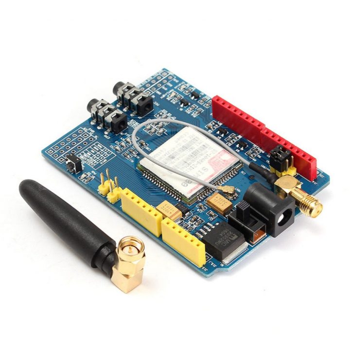
Brief Intro about SIM900 GSM GPRS Shield
GSM is a global system for mobile communication. Hence, to communicate with the computing devices, the GSM SIM needs a module. SIM900 is considered one of the best modules of today’s time. It’s a quad-band module that works perfectly with four frequencies, which are 850, 900, 1800, and 1900 MHz. The device is so compact and is compatible with Arduino. It easily allows sending SMS, MMS, etc. Moreover, it also supports audio through UART by using AT commands. Besides, it contains microphones and headphone jacks for phone calls. The sensor needs the 5Volts power supply and draws 2Amp of current.
Hardware Required
| S.no | Component | Value | Qty |
|---|---|---|---|
| 1. | Arduino UNO | – | 1 |
| 2. | USB Cable Type A to B | – | 1 |
| 3. | Jumpier Wire | – | – |
| 4. | GSM GPRS Shield | SIM900 | 1 |
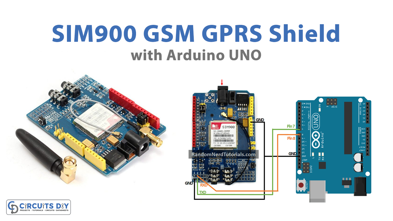
Circuit Diagram

Connection Table
| Arduino | SIM900 GSM GPRS Shield |
|---|---|
| GND | GND |
| D7 | TX |
| D8 | RX |
Arduino Code
// Circuits DIY
 // For Complete Details Visit -> https://circuits-diy.com
#include <SoftwareSerial.h>

// Configure software serial port
SoftwareSerial SIM900(7, 8);

void setup() {
  // Arduino communicates with SIM900 GSM shield at a baud rate of 19200
  // Make sure that corresponds to the baud rate of your module
  SIM900.begin(19200);
  // Give time to your GSM shield log on to network
  delay(20000);

  // Send the SMS
  sendSMS();
}

void loop() {

}

void sendSMS() {
  // AT command to set SIM900 to SMS mode
  SIM900.print("AT+CMGF=1\r");
  delay(100);

  // REPLACE THE X's WITH THE RECIPIENT'S MOBILE NUMBER
  // USE INTERNATIONAL FORMAT CODE FOR MOBILE NUMBERS
  SIM900.println("AT+CMGS=\"+XXXXXXXXXXXX\"");
  delay(100);

  // REPLACE WITH YOUR OWN SMS MESSAGE CONTENT
  SIM900.println("Message example from Arduino Uno.");
  delay(100);

  // End AT command with a ^Z, ASCII code 26
  SIM900.println((char)26);
  delay(100);
  SIM900.println();
  // Give module time to send SMS
  delay(5000);
}
Working Explanation
First, you need to insert your SIM card into the GSM module. Then, connect GSM GPRS Shield with Arduino UNO. Now, upload the given code on an Arduino board. After that, give the external 5Volts of power supply to the module. Then, press the power key of the GSM Module for 2 seconds. The LED present in the module will start glowing. And, when the sensor finds the networks, it will start blinking every three seconds. Now it is time to send or receive messages and phone calls with your Arduino through the code. However, In this tutorial, we only have formulated the code to send the messages. But, you can also receive messages, and send or receive phone calls by using different programming codes. So, to make different codes, you need to understand the above-given code.
Code Explanation
- Include the serial.h library, to enable the serial communication on pins 7 and 8, which are the receiver and transmitter pins.
- In the void setup, initialize the module by SIM900. begin ( ). Now the code has defined the delay to give the time to GSM for logging on to the required network. Then there is a command send SMS ( ) to send the message
- In a void loop, send SMS( ) function has been created. The function uses the AT+CMGS to send the message. Remember, the command has Xs in it. Replace those Xs with the SIM’s phone number. SIM.900. println( ) is used to send the message written in the bracket. Write whatever you want. In our case, we have written “Message example from Arduino UNO”. The code then gives the delay to send the message. After that, the message will be received on our mobile phone.
Application and Uses
- Firstly, it can be used in home automation systems to send messages to the appliances
- Secondly, it can be used in intruder alarm circuits. Hence, send the notification for alert
- Also, in the weather stations
- Moreover, it can be utilized in other devices to send or receive data.